
Versatile system for conditioning slurry in CMP process

a technology of slurry conditioning and cmp, which is applied in the direction of cleaning using liquids, other chemical processes, lapping machines, etc., can solve the problems of copper being difficult to etch in the majority of the semiconductor process flow, affecting the efficiency of the slurry conditioning process, and affecting the quality of the slurry, etc., to achieve optimal slurry composition, reduce or eliminate slurry nonconformities, and optimize the effect of slurry mixing or conditioning

Active Publication Date: 2006-02-09
TEXAS INSTR INC
View PDF7 Cites 7 Cited by
  • Summary
  • Abstract
  • Description
  • Claims
  • Application Information

AI Technical Summary

Benefits of technology

The present invention provides a system for mixing and conditioning multi-component slurries used in chemical mechanical polishing (CMP) of semiconductor wafers. The system uses a conditioning component that can be added onto existing CMP apparatus or formed as part of the apparatus. The conditioning component applies intense, non-damaging energy to the slurry components, resulting in a uniform mixture that can be used for polishing without the need for labor-intensive monitoring and adjustment. The system also allows for immediate mix adjustment and provides consistent and reliable CMP results. Overall, the present invention offers an easy, efficient, and cost-effective solution for mixing and conditioning slurries in CMP.

Problems solved by technology

The increased packing density of the integrated circuit generates numerous challenges to the semiconductor manufacturing process.
Unfortunately, copper is very difficult to etch in most semiconductor process flows.
Where slurries are left unused while sitting in storage or transport, even for relatively small amounts of time (e.g., 1 hour), a certain degree of degradation begins.
These and other related phenomena degrade the consistency and efficacy of the slurry over time—resulting in inconsistent CMP results wafer-to-wafer and lot-to-lot.
Such deficiencies can cause uneven polishing, scratches or other related anomalies.
This, in turn, can cause a number of yield and reliability problems.
Typically, re-mixing is of limited effectiveness, and both approaches introduce a high level of labor and material costs to the manufacturing process.
Conventional point-of-use mixing also causes certain issues for manufacturers.
Utilizing such an approach, a manufacturer cannot be sure that a full and consistent mixing, or an even polish, has occurred.
Depending upon the slurry components used, this impact stress can cause component shear—resulting in the formation of additional agglomerations and other non-conformities in the slurry.
Furthermore, such mixing is usually brief—not allowing enough time for a full mixing or beneficial pre-reaction of slurry components (i.e., conditioning), depending upon the components used.
These and other similar conventional approaches thus result in a number of CMP irregularities.
Agglomerations, gels, settled particulate matter and other non-conformities occurring in such conventional systems could overpolish, under polish, mar or scratch device structures on a wafer surface.
If not recognized, these irregularities detrimentally skew the CMP process.
Either way, product yield and process costs are negatively impacted.
Moreover, such conventional systems—whether premixed or point-of-use—are typically static in nature, providing for only a single slurry formulation during CMP.
Given the methods and apparatus of most conventional systems, however, wafer-to-wafer modification would be an exceptional circumstance rather than a routine operation—as it would add a number of time and labor-intensive steps to the process (e.g., stopping processing lines, purging component reservoirs and conduits, refilling).
For similar reasons, intra-wafer modification of slurry formulation would be commercially impractical, if not impossible.

Method used


Image

  • Versatile system for conditioning slurry in CMP process
  • Versatile system for conditioning slurry in CMP process
  • Versatile system for conditioning slurry in CMP process

Examples


Embodiment Construction

[0025] While the making and using of various embodiments of the present invention are discussed in detail below, it should be appreciated that the present invention provides many applicable inventive concepts, which can be embodied in a wide variety of specific contexts. The present invention is hereafter illustratively described in conjunction with the mixing and conditioning of polishing slurries and slurry components, for use in chemical mechanical polishing systems. The specific embodiments discussed herein are, however, merely demonstrative of specific ways to make and use the invention and do not limit the scope of the invention.

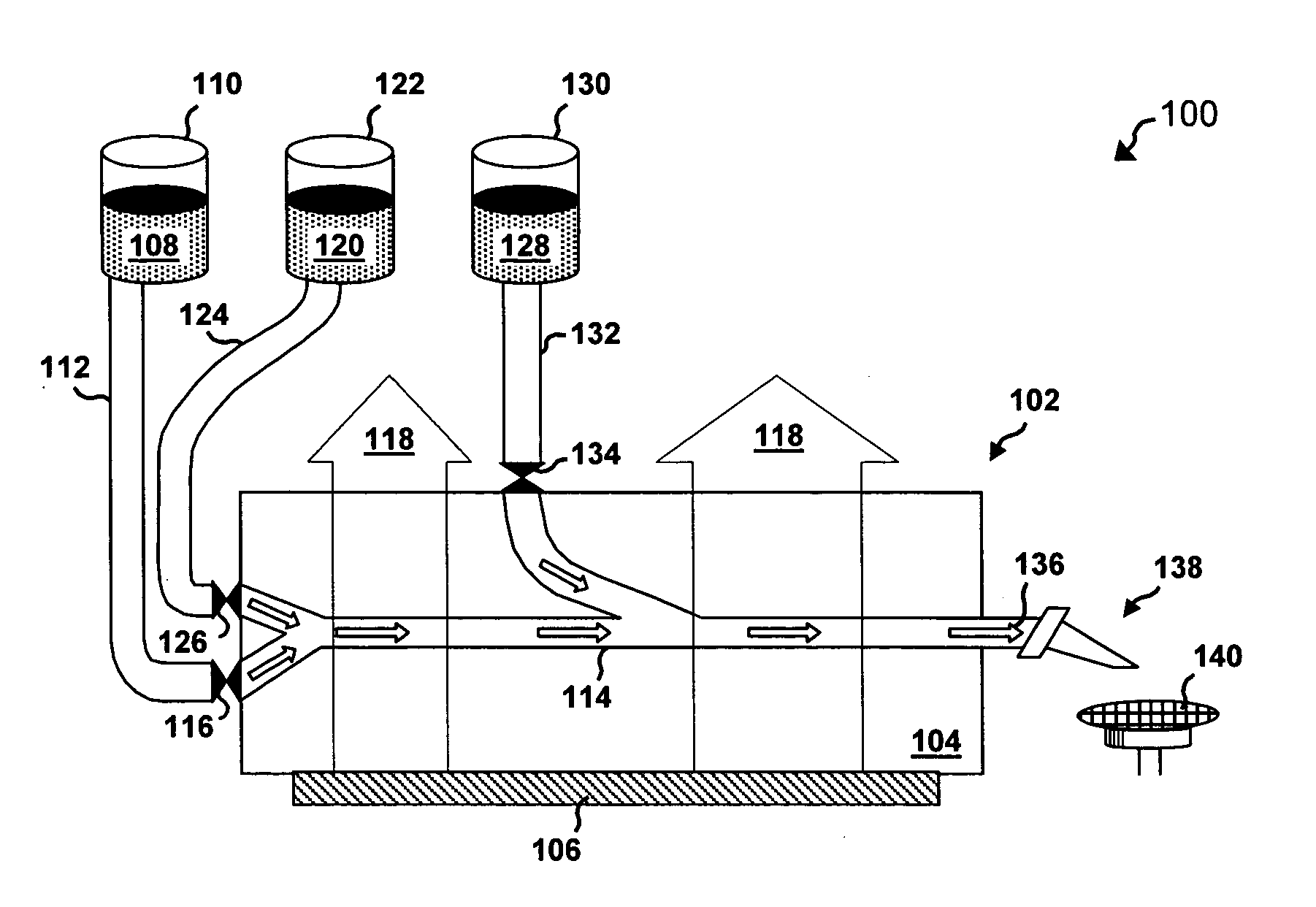
[0026] The present invention provides a versatile system, comprising a number of apparatus and methods, for point-of-use mixing or conditioning of multi-component slurries used in CMP. The system of the present invention may also be utilized to remix or recondition premixed slurries that have been stored for some time.

[0027] Comprehending certain com...


PUM

PropertyMeasurementUnit
timeaaaaaaaaaa
energyaaaaaaaaaa
energy transmissionaaaaaaaaaa

Abstract

The present invention provides a system (100) for conditioning multi-component slurries utilized in chemical mechanical polishing (CMP) of semiconductor wafers (140). The system provides a first slurry component (108), and a second slurry component (120). A conditioning component (102) has first and second inlets, and an outlet operatively coupled to a dispensing system (138). First and second flow control components (116, 126) are operably intercoupled between the first and second inlets and the first and second slurry components, respectively. The system further provides a megasonic energy source (106), adapted to generate an energy field (118) across the conditioning component. A conveyance component (114) conducts the slurry components from the inlets through the energy field, and delivers a final mixture (136) of multi-component slurry to the outlet.

Description

TECHNICAL FIELD OF THE INVENTION [0001] The present invention relates generally to the field of semiconductor devices and, more particularly, to apparatus and methods for optimal point-of-use mixing or conditioning of multi-component slurries for chemical-mechanical polishing (CMP). BACKGROUND OF THE INVENTION [0002] The continual demand for enhanced integrated circuit performance has resulted in, among other things, a dramatic reduction of semiconductor device geometries, and continual efforts to optimize the performance of every substructure within any semiconductor device. A number of improvements and innovations in fabrication processes, material composition, and layout of the active circuit levels of a semiconductor device have resulted in very high-density circuit designs. Increasingly dense circuit design has not only improved a number of performance characteristics, it has also increased the importance of, and attention to, semiconductor material properties and behaviors. [0...

Claims


Application Information

Patent Timeline
Patent Type & Authority Applications(United States)
IPC IPC(8): C09K3/14
CPCB24B57/02B24B37/04Y10S134/902
Inventor STARK, DAVID A.SCHULTZ, LAURENCE D.MURPHY, NEAL T.
Owner TEXAS INSTR INC
Learn More