
Cigarette lighter with improved safety properties

a safety property and lighter technology, applied in the field of cigarette lighters, can solve the problems of small flames, such as those found in cigarette/utility lighters, incipient fires, and significant fire hazards, and achieve the effect of improving safety properties and improving ignition propensity

Inactive Publication Date: 2006-02-02
MARYLAND UNIV OF
View PDF19 Cites 8 Cited by
  • Summary
  • Abstract
  • Description
  • Claims
  • Application Information

AI Technical Summary

Benefits of technology

[0027] It is a major object of the present invention to provide a cigarette lighter which demonstrates improved ignition propensity and increased safety properties.
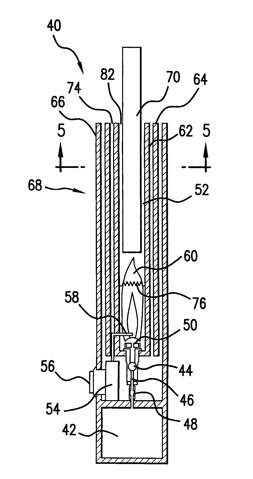
[0030] It is also an object of the present invention to provide a cigarette lighter in which a generated flame is contained completely in the combustion chamber which envelops the flame. Since no flame extends outside the combustion chamber, the cigarette has to be introduced into the combustion chamber for contact with the produced flame and resultant ignition. The flame recession (combustion chamber) acts as a medium to absorb energy from the flame while increasing the distance between the flame source and the exit of the hot gases as well as significantly improving exit gas properties.
[0033] A flame stabilizer in the form of a mesh made of titanium wire is introduced in the inner tube a predetermined distance from the exit opening in order to limit the insertion of the cigarette into the combustion chamber to prevent unwanted extinction of the flame which can be caused by the cigarette being brought too close to the source of the flame.

Problems solved by technology

Small flames, such as those found in candles, matches, cigarette / utility lighters and the incipient fire pose a significant fire hazard.
These small flames can release enough thermal energy to cause unwanted ignition and sustain burning.
Small ignition sources are dangerous and may produce a fire that may remain unnoticed for a significant period of time.
Cigarette lighter flames produce a high risk of ignition and therefore need special consideration.
These additional mechanical child safety features however do nothing to resolve the unwanted ignition propensity of the lighter flame.
Studies conducted by the National Association of State Fire Marshals (NASFM), such as the Juvenile Firesetter Program, have shown that these features are insufficient for reducing unwanted ignition by juveniles ages 4 to 16.
Additionally, the American Society for Testing and Materials (ASTM) standard for regulation of cigarette lighters, ASTM F400-00, is qualitative in nature with respect to unwanted ignition propensity and does not characterize the increased hazard of many new cigarette lighter designs.
There is very little previous work characterizing the ignition hazard from cigarette lighters.
Lighter nozzles that produce higher plume temperatures correspondingly have a higher risk of ignition than those with lower temperatures assuming comparable velocities.
They found significant scatter in the heat flux data with only limited agreement with the Alpert's ceiling jet theory.
These profiles are useful for calculating heat flux to a ceiling surface, however, the studies do not evaluate the steady state solution for a thermally thin ceiling.
This study illustrates that there is a negligible difference between the transient and the steady state ceiling jet flow however, it does not characterize heat transfer to the ceiling.
Unfortunately, much of the ignition research conducted has focused on thermally thick or semi-infinite solids.
Relatively little work has been done with thermally thin solids.
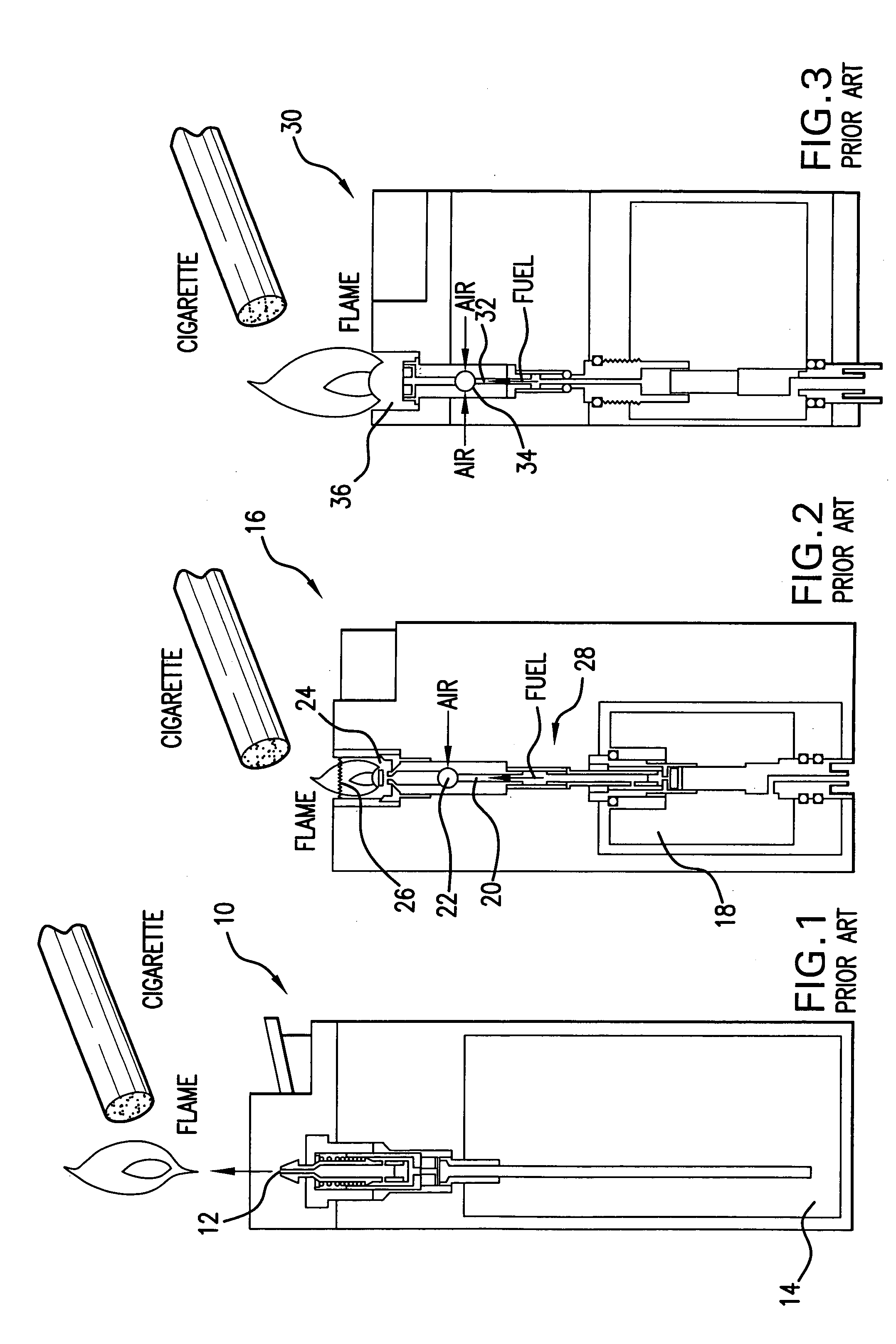
All three prior art lighters in FIGS. 1-3, have a generally high degree of hazardousness due to the fact that the flame either is generated external the cigarette lighter or extends beyond the lighter, thus making ambient items susceptible to the ignition.

Method used


Image

  • Cigarette lighter with improved safety properties
  • Cigarette lighter with improved safety properties
  • Cigarette lighter with improved safety properties

Examples


Embodiment Construction

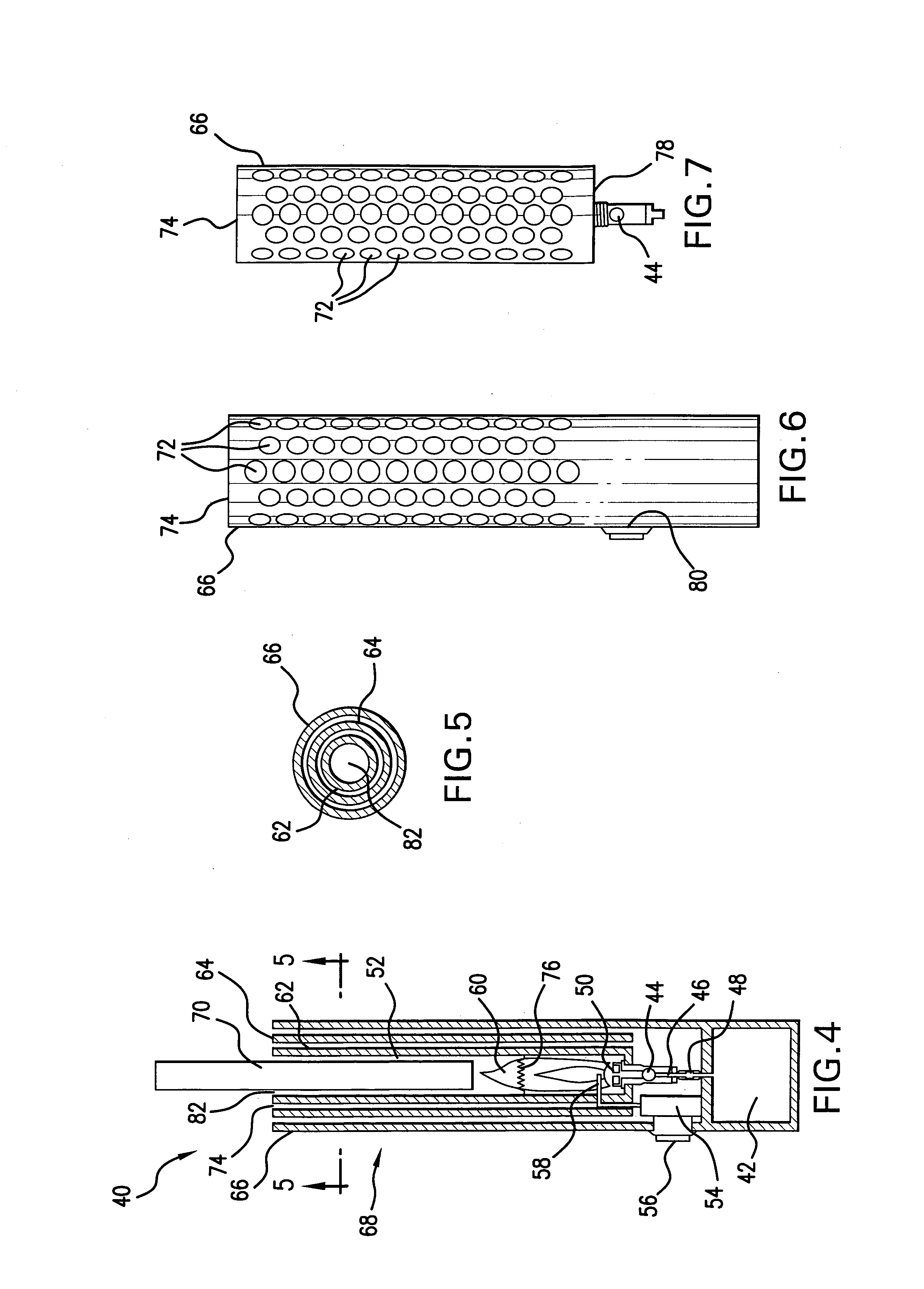
[0048] Referring to FIG. 4, cigarette lighter 40 of the present invention includes a fuel reservoir 42 containing fuel. The fuel is delivered to an air mixing chamber 44 through the orifice 46. The fuel reservoir 42 is connected to the orifice 46 by a fuel connection tube 48. In the air mixing chamber 44, the fuel mixes with the air to form the air-fuel mixture which is delivered to a burner nozzle 50 and is injected therethrough into a combustion chamber 52.

[0049] A piezoelectric spark device 54 is operatively coupled to an operation button 56 for actuation / deactuation. Upon actuation, the piezoelectric spark device 54 generates a discharge which is delivered through a spark ignition wire 58 into the combustion chamber 52 filled with the fuel-air mixture. The discharge from the spark ignition wire 58 ignites the fuel-air mixture in the combustion chamber and produces a flame 60 therein.

[0050] The combustion chamber 52 consists of three concentric vented stainless steel tubes 62, ...


PUM


Abstract

A cigarette lighter with improved safety property includes a combustion chamber formed as a receptacle in which a cigarette to be lit is inserted. The receptacle is formed of three concentric vented tubes. The combustion chamber is shaped and dimensioned in a manner to completely envelop the flame produced in the combustion chamber, and to prevent any objects with dimensions larger than diameter of a cigarette to be received in the combustion chamber. A flame stabilizer is secured in the inner tube of the receptacle unit at a predetermined distance from the burner in order to limit the insertion of the cigarette and to prevent the unwanted extinction of the flame if the cigarette is inserted too close to the source of the flame.

Description

REFERENCE TO RELATED APPLICATIONS [0001] This Utility Patent Application is based on Provisional Patent Application No. 60 / 592,876 filed Jul. 30, 2004.FIELD OF THE INVENTION [0002] The present invention relates to cigarette lighters and more in particular, to systems for improving fire safety considerations of cigarette lighters. [0003] In overall concept, the present invention relates to a cigarette lighter which generates a flame completely enveloped within the combustion chamber of the cigarette lighter, whereby the cigarette being lit is brought into contact with the flame within the combustion chamber. [0004] Further, the present invention relates to a cigarette lighter equipped with a receptacle designed according to the geometry of a cigarette such that only objects of similar geometry or smaller than a cigarette may be inserted into the receptacle. In this manner, the cigarette lighter provides local heating to the cigarette, and as the result, reduced heating to objects sur...

Claims


Application Information

Patent Timeline
IPC IPC(8): F23Q2/00
CPCF23Q2/163
Inventor WILLIAMSON, JUSTIN WADEMARSHALL, ANDRE W.QUINTIERE, JAMES G.
Owner MARYLAND UNIV OF
Learn More