Steam power plant

Inactive Publication Date: 2006-02-02
SIEMENS AG
View PDF7 Cites 4 Cited by
  • Summary
  • Abstract
  • Description
  • Claims
  • Application Information

AI Technical Summary

Benefits of technology

[0014] A steam power plant according to the invention can use higher steam temperatures than the prior art, which can contribute to an increase in the efficiency of the steam power plant.
[0016] The use of hydrogen as fuel offers the advantage in particular that—if the hydrogen, as is generally customary, has been produced by reforming or gasification from a hydrocarboncarbon dioxide which is produced can be blocked with relatively little outlay on energy as early as during production of the hydrogen during reforming or gasification of a hydrocarbon, and in this way the formation of an acidic steam mixture within the steam turbine and / or other components of the steam power plant is avoided from the outset.
[0019] In a further preferred embodiment of the invention, combustion products which are produced can be removed from the flow of steam by means of a condenser connected downstream of the steam turbine.
[0024] The internal additional firing which is realized by means of the firing device of a steam power plant according to the invention can be made available very quickly during operation of the steam turbine. For this purpose, it is merely necessary to ignite fuel which has been introduced into the combustion chamber; in particular, the heat-up times of known heat exchanger surfaces are eliminated.
[0025] Furthermore, a steam power plant according to the invention offers the advantage that combustion products and / or exhaust gas do not necessarily have to be discharged from the combustion chamber by means of a separate discharge device, since they can be entrained by the flow of steam and removed elsewhere in the steam circuit, for example the abovementioned condenser. Moreover, the invention makes it possible to reach a higher steam temperature without having to change the design of the steam generator.
[0026] A steam power plant according to the invention can in particular also be used to provide energy at peak load times or to boost the mains frequency of an electrical energy supply network; a steam power plant according to the invention offers the possibility of rapid power control and can be used very flexibly.

Problems solved by technology

Since in the heat exchangers which are known from the prior art and are used in steam generators of known steam power plants the energy of a hot gas is transferred to the medium to be heated by means of a material of the heat exchanger surface that has been heated by the hot gas, the quantity of energy which can be transferred to the medium to be heated, for example water and / or steam, is limited by the materials properties of the heat exchanger surface.
Therefore, in known steam power plants, the permissible steam temperatures are limited, since the heat exchanger surface which transfers the thermal energy cannot be heated to any desired temperature level on account of its material properties and associated thermal loading limits.
Furthermore, the transfer of heat from hot gas to the medium that is to be heated is subject to a delay caused substantially by the required heating time of the heat exchanger surface.

Method used


Image

  • Steam power plant
  • Steam power plant

Examples


Embodiment Construction

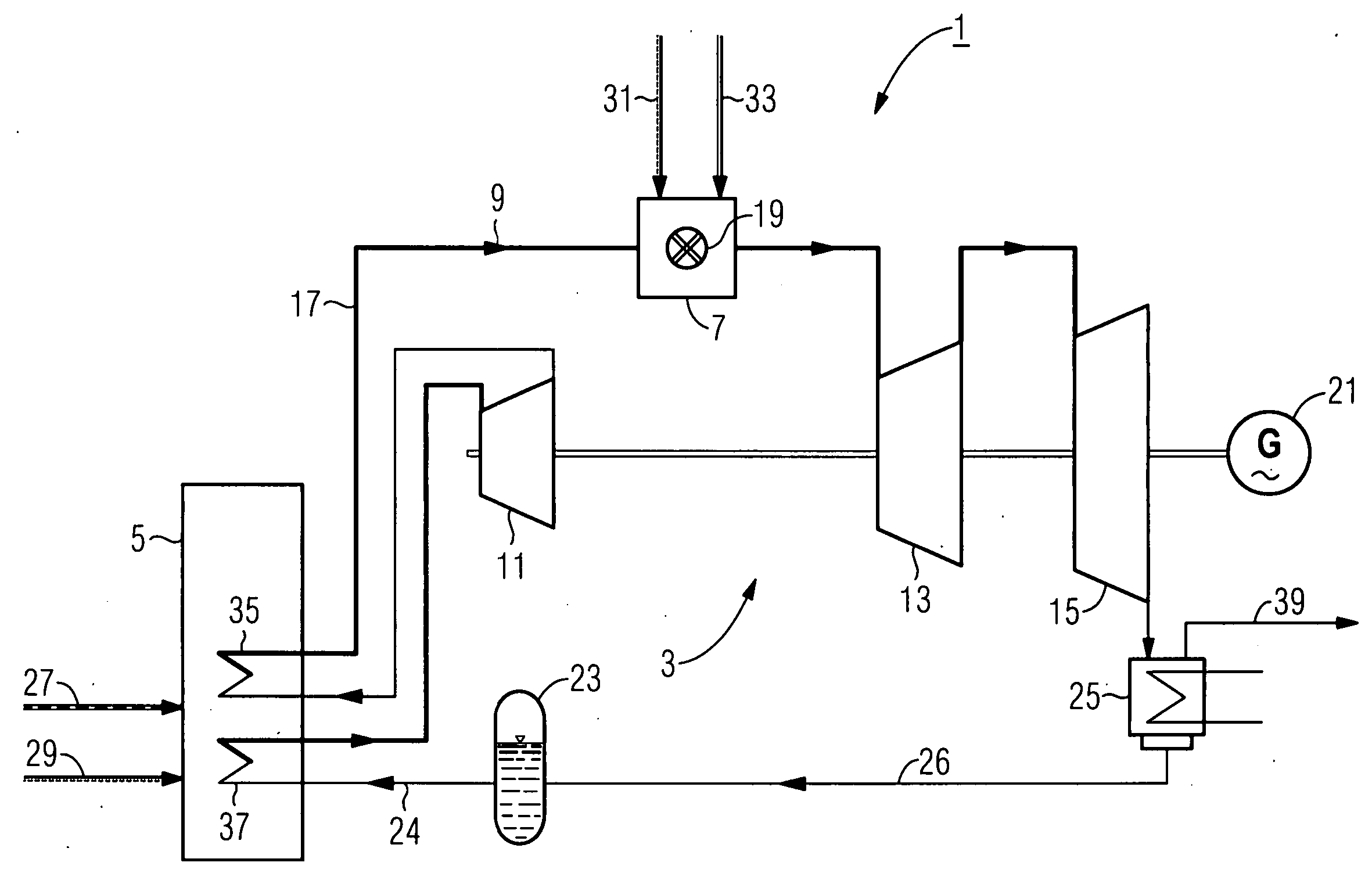
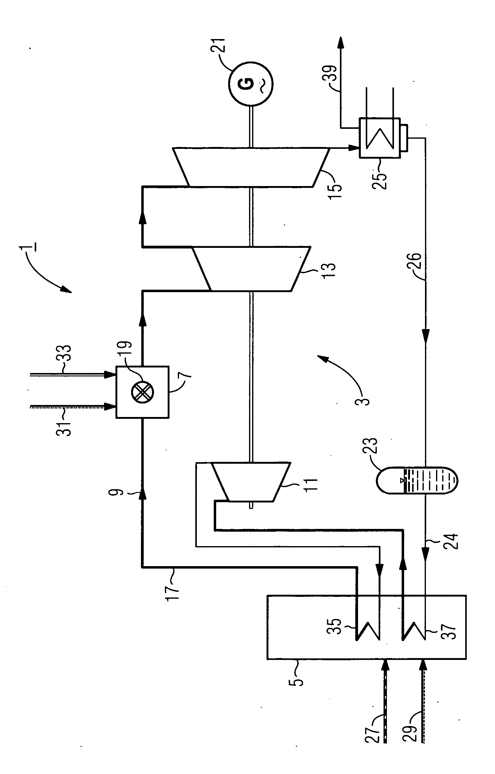
[0029] The FIGURE illustrates a steam power plant 1 according to the invention, which comprises a steam turbine 3 coupled to a generator 21, as well as a steam generator 5.

[0030] The steam turbine 3 is of three-stage construction and includes a first turbine stage 11, a second turbine stage 13 and a third turbine stage 15, which are respectively designed as high-pressure stage, medium-pressure stage and low-pressure stage.

[0031] In the present exemplary embodiment shown in the FIGURE, the steam generator 5 is a boiler fired by means of coal 27, to which combustion air 29 is fed in order to maintain the coal firing.

[0032] A heating surface 37 is arranged in the region of the hot end of the steam generator 5, and a reheater heating surface 35 is arranged in a lower-temperature region of the steam generator 5.

[0033] The heating surface 37 is used to heat feedwater 24 from a feedwater vessel 23 in the steam generator 5 in such a manner that operating steam can be fed to the first tu...


PUM


Abstract

The invention relates to an inventive steam power plant comprising at least one steam turbine and a steam generator. According to the invention, a firing device is located downstream of the steam generator and upstream of the steam turbine and / or downstream of a first turbine phase and upstream of a second turbine phase of the stream turbine in the direction of the stream flow and the steam flow can be heated in a combustion chamber of the firing device by being mixed with a heating gas that can be generated in the combustion chamber.

Description

CROSS REFERENCE TO RELATED APPLICATION [0001] This application is the US National Stage of International Application No. PCT / EP2003 / 005123, filed May 15, 2003 and claims the benefit thereof. The International Application claims the benefits of European Patent application No. 02014453.1 EP filed Jun. 28, 2002, both of the applications are incorporated by reference herein in their entirety. FIELD OF THE INVENTION [0002] The invention relates to a steam power plant having at least one steam turbine and a steam generator. BACKGROUND OF THE INVENTION [0003] In known steam power plants, operating steam for a steam turbine is generally generated in a steam generator, the energy contained in a hot gas being released to one or more heat exchangers which are fed with water, so that operating steam can be generated by heating this water, or which are fed with steam, so that the steam can be superheated by means of a said heat exchanger; superheating of this type, in known steam turbines, takes...

Claims


Application Information

Patent Timeline
IPC IPC(8): F02C3/30F01K25/00
CPCF01K25/005Y02E20/34
Inventor HABERBERGER, GEORGKAIL, CHRISTOPH
Owner SIEMENS AG
Why Eureka
Try Eureka