
Active dose reduction device and method

a technology of active dose and reduction device, which is applied in the field of active dose reduction device and method, can solve the problems of large amount of x-ray radiation, detrimental “tail” of x-rays, and detrimental imaging value, and achieve the effects of reducing the overall cost and volume of the device, simplifying the control circuitry, and increasing control reliability

Inactive Publication Date: 2006-01-26
COMM & POWER IND CANADA
View PDF5 Cites 6 Cited by
  • Summary
  • Abstract
  • Description
  • Claims
  • Application Information

AI Technical Summary

Benefits of technology

"The present invention relates to an improved x-ray imaging system that reduces the amount of X-rays generated during the imaging process. The invention includes a plurality of electronic cells that prevent the flow of current until they are overvoltaged and become conductive. The overvoltaging of the cells can be performed on a single cell by applying a pulse voltage, which forces the cell from its first state to its second state. The system also includes an overvoltag circuit that causes at least one cell to exceed its threshold voltage and change from its first state to its second state, thereby discharging stored energy in the system and reducing the X-rays generated during the imaging process. The invention provides a faster and safer way to decrease the X-ray dosage and lower the cost of the X-ray imaging system."

Problems solved by technology

Radiographic imaging requires large amounts of x-ray radiation for short periods of exposure time.
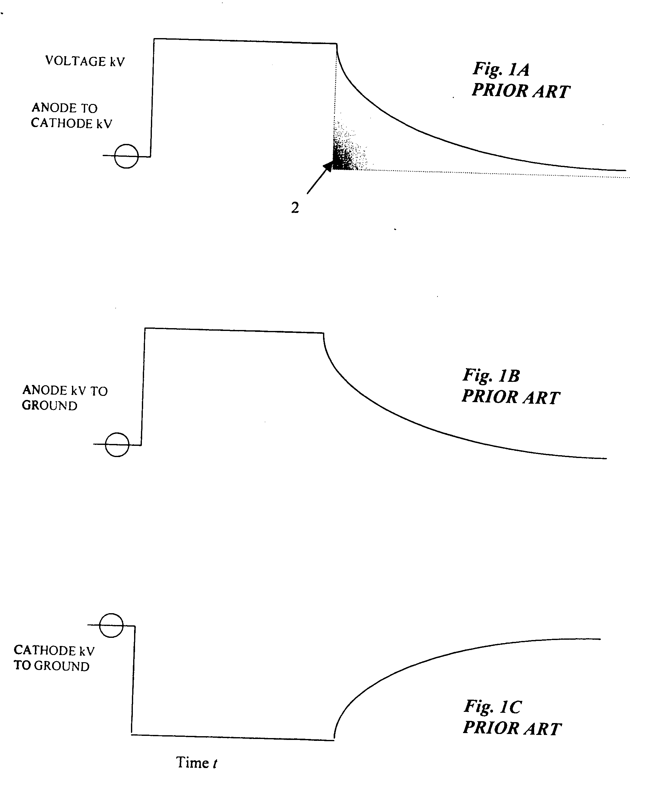
The “tail” of x-rays is detrimental for several reasons.
Furthermore, the “tail” of x-rays is also detrimental during the x-ray imaging as it generally causes additional detected radiation which is not useful or may have detrimental imaging value because it has a diminishing waveform characteristic.
This effect increases exposure time which increases motion artefacts to the displayed image.
However, grid-type tubes had limited radiographic abilities at higher power levels and at higher voltage thereby limiting grid-type x-ray tubes to lower voltage potentials than non-grid tubes.
Another disadvantage of grid-type x-ray tubes is that certain regulatory agencies require a mechanical “flapper” to be added to the x-ray tube port to prevent exposing patients and staff to continuous x-ray should the grid bias be lost.
Furthermore, use of the grid-type tubes increased the operating costs of the overall x-ray imaging system because grid-type tubes require a third control line which many systems do not provide and the replacement cost of a grid-type x-ray tube is much higher than non-grid tubes.
While the Beland device operates relatively well, it suffers from the disadvantage that there is a time lag required for each of the switches to activate gates in the series of switches.
While the Sammon device is relatively quick, it suffers from the disadvantage that it requires two xenon tubes which are expensive, must be periodically replaced, and may exhibit changing characteristics over time and use.
Also, a relatively large voltage is required to ionize the gas in the xenon tubes increasing the overall cost of operation and the heat generation.

Method used


Image

  • Active dose reduction device and method
  • Active dose reduction device and method
  • Active dose reduction device and method

Examples


Embodiment Construction

[0044] Preferred embodiments of the invention and its advantages can be understood by referring to the present drawings. In the present drawings, like numerals are used for like and corresponding parts of the accompanying drawings.

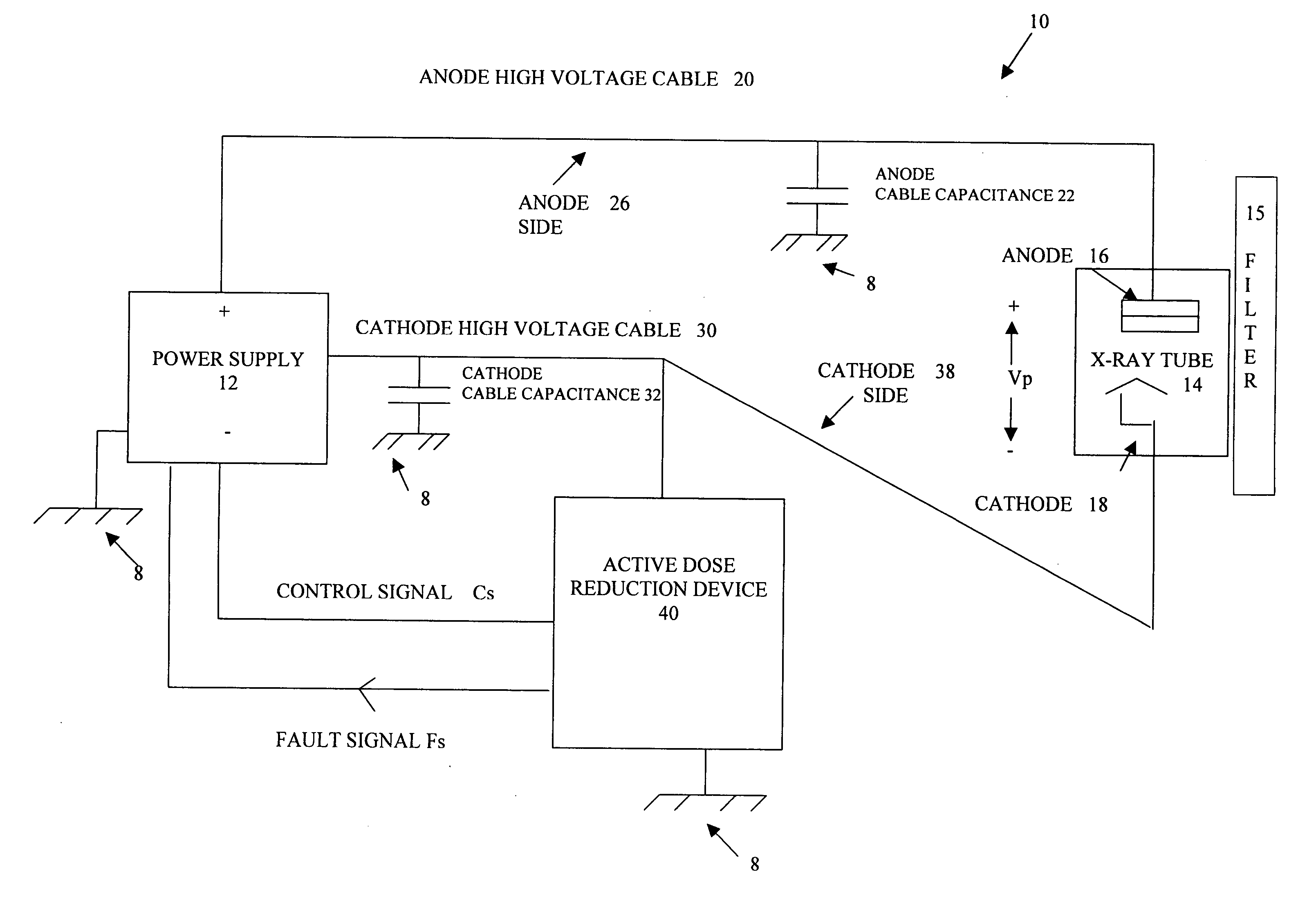
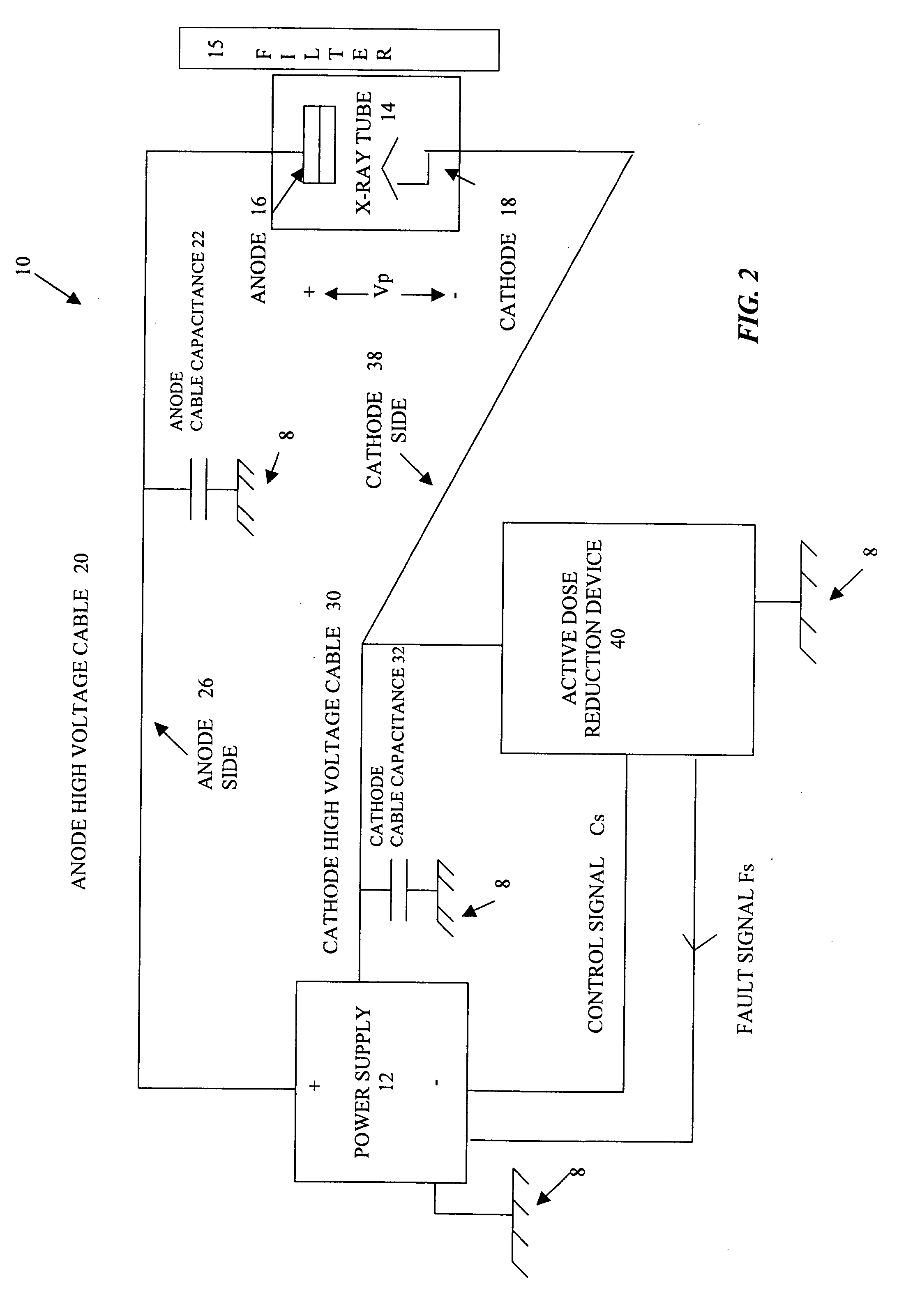
[0045]FIG. 2 illustrates an imaging system, shown generally by reference numeral 10, comprising an active dose reduction device, shown generally by reference numeral 40, according to one embodiment of the present invention. As illustrated in FIG. 2, the imaging system 10 comprises a power supply 12, such as a generator, for supplying power to an x-ray tube, as shown generally by reference numeral 14, at a preselected voltage Vp. The power supply 12 supplies the power to the x-ray tube 14 through an anode high voltage cable 20, connected to anode 16 of the x-ray tube 14, and a cathode high voltage cable 30, connected to the cathode 18 of the x-ray tube 14. Accordingly, the anode high voltage cable 20 and the cathode high voltage cable 30 represent a cable ...


PUM


Abstract

An active dose radiation device and method decreases the amount of x-rays which may be generated by an x-ray tube following termination of the x-ray exposure. One component of the x-ray system is connected to the device which has a plurality of electronic cells that can be overvoltaged from a first state, where they are less conductive, to a second state, where they are highly conductive. A voltage pulse generator overvoltages a first cell in the plurality of cells at termination of an x-ray exposure. Overvoltaging the first cell causes a cascading effect which eventually overvoltages all of the cells and changes the state of the cells from the first less conductive state to the second highly conductive state. In the second highly conductive state, the cells can conduct current from at least one component of the x-ray system to ground thereby reducing x-rays generated by the x-ray tube and reducing the x-ray dosage from the imaging system after the x-ray exposure has been completed. The plurality of cells automatically reverts to the first state once current passing through the cells decreases below a threshold current level. The plurality of cells are connected to only the anode side 26 or the cathode side 38 of the x-ray imaging device in order to discharge energy from only one side to ground which results in a sufficient decrease in the voltage across the x-ray tube to prevent generation of active dosage of x-rays which may penetrate the patient.

Description

FIELD OF THE INVENTION [0001] The present invention relates in general to a device and method for decreasing the active dosage of x-rays during x-ray imaging. More particularly, the present invention relates to a device and method for reducing excess stored energy, such as stored capacitive energy, from at least some of the components of the x-ray imaging system to reduce the x-ray dosage from the imaging system. BACKGROUND OF THE INVENTION [0002] During x-ray imaging, x-rays are produced through the generation of electrons by thermionic emission from a cathode, often a tungsten filament, and the acceleration of these electrons within an x-ray tube towards an anode, which causes the emission of x-rays. The emission intensity of the x-rays from the x-ray tube is controlled by the filament current and by the selected voltage potential differential between the anode and the cathode. The selected voltage potential is generally several tens of thousand kilovolts (kV). [0003] There are di...

Claims


Application Information

Patent Timeline
Patent Type & Authority Applications(United States)
IPC IPC(8): H05G1/44
CPCH05G1/30A61B6/508H05G1/56H05G1/32
Inventor CUNNINGHAM, JAMES ALLANNEYSMITH, PETER FRANCIS
Owner COMM & POWER IND CANADA
Learn More