Diffraction-based optical grating structure and method of creating the same

Inactive Publication Date: 2006-01-26
OPSEC SECURITY GROUP
View PDF13 Cites 64 Cited by
  • Summary
  • Abstract
  • Description
  • Claims
  • Application Information

AI Technical Summary

Benefits of technology

[0021] It is another object of the present invention to provide an OVD which is easy and economical to fabricate.
[0022] It is another object of the present invention to arrange the elements of the OVD in an array which exhibits further novel optical effects, such as, for example, a pattern of color change.
[0027] It is yet another object to provide such a device and method which is efficient and cost-effective.
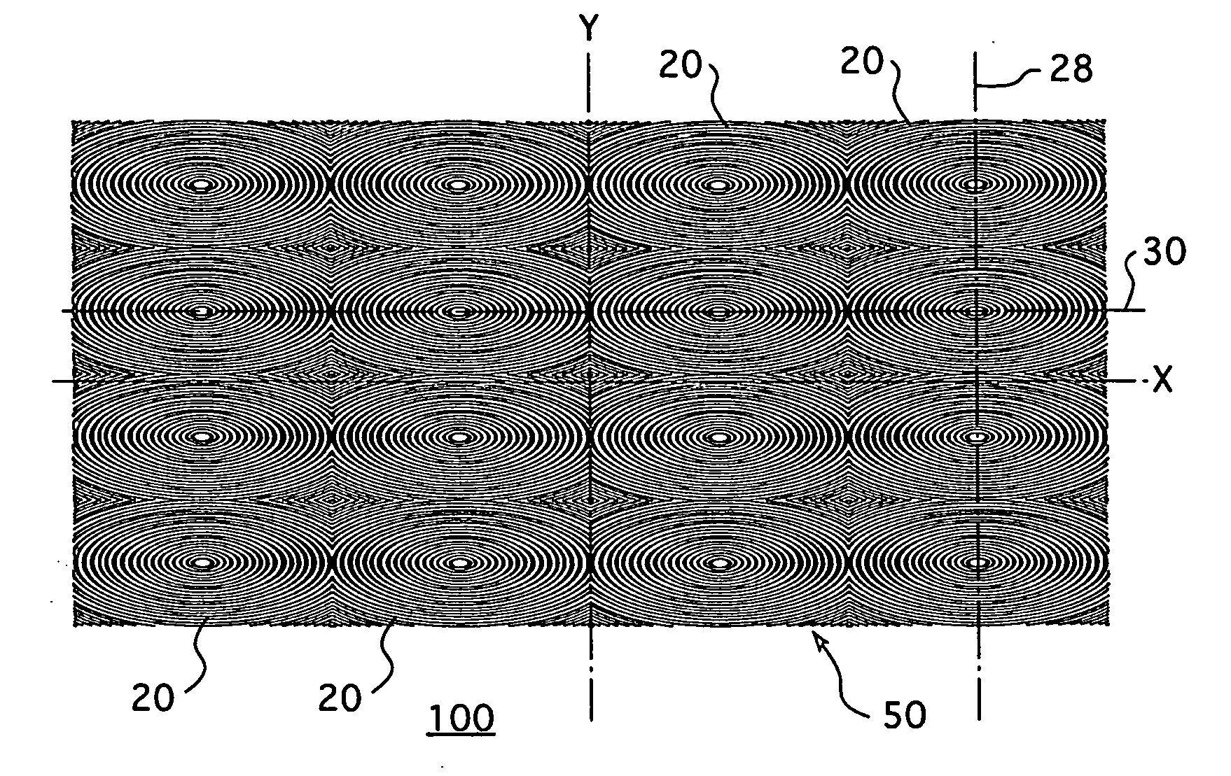
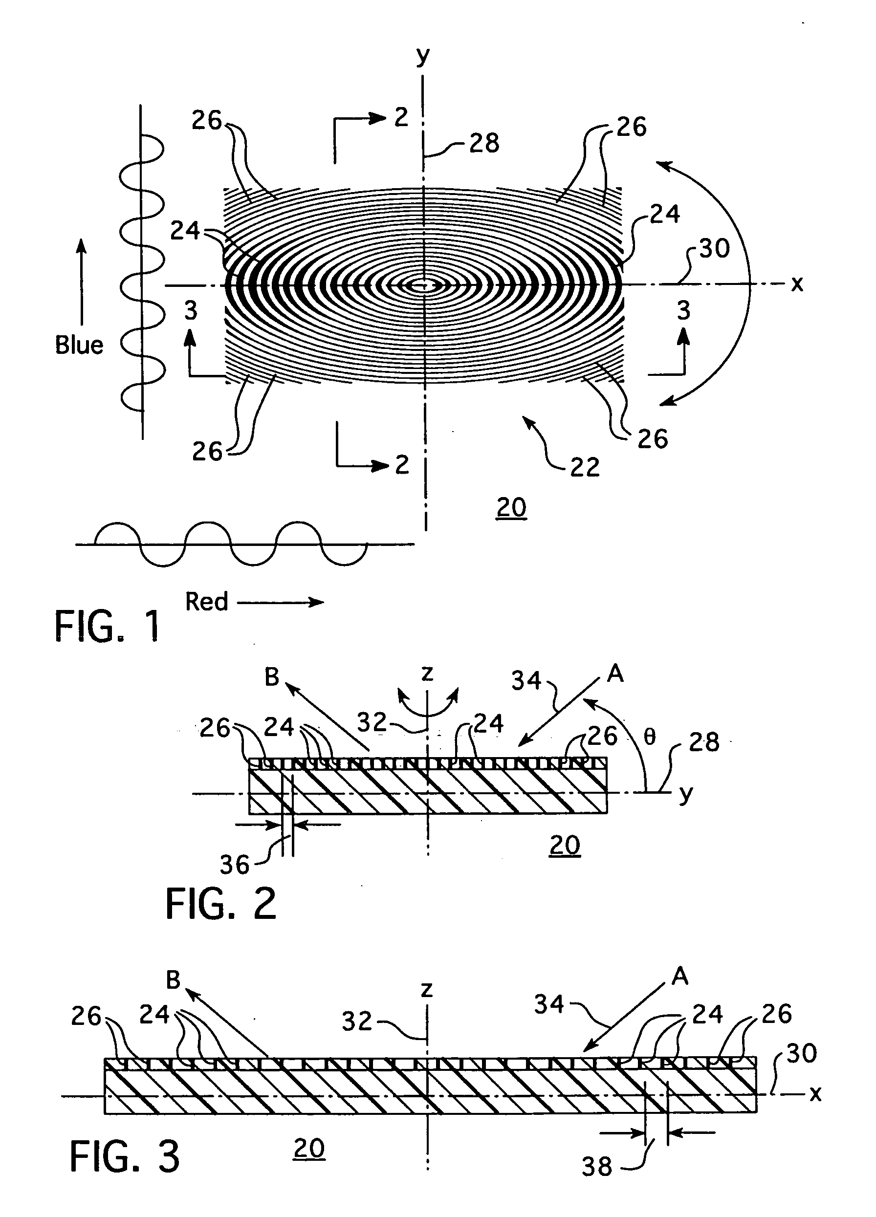
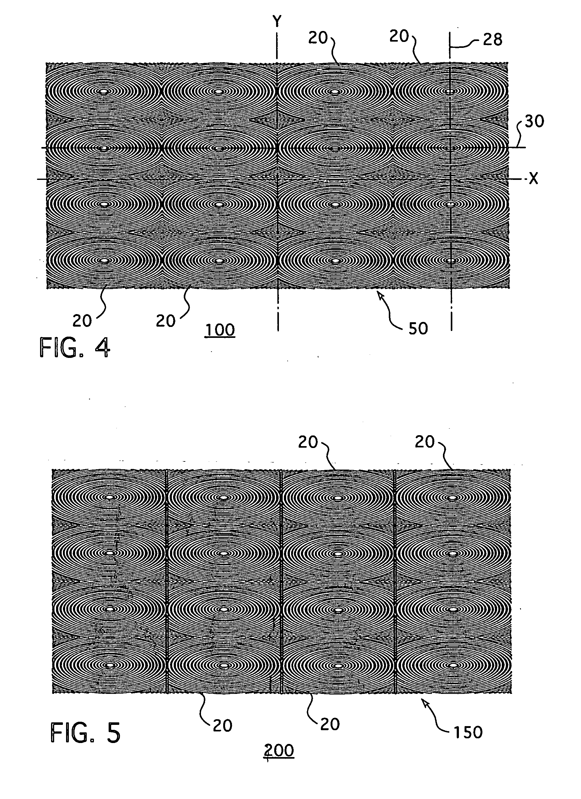
[0028] The present invention provides optical elements including a light diffracting optical grating structure. Light passing through the diffraction gratings will diffract into its various wavelengths, thereby resulting in-optical effects, color change, such as the location from which the elements are viewed is changed. The elements may be arranged in any suitable orientation to form an array, thereby creating an OVD. The OVD may be encoded to include, for example, a specific color change pattern or rate of color change that may be visually identified by the human eye or alternatively be machine readable. Encoding of the OVD may include information such as, for example, without limitation, a pattern or information such as a personal identification number, for example, a social security number, credit card number or membership identification number. It will be appreciated that all of this may be accomplished while facilitating the advantageous use of combinations of additional optically variable devices such as holograms, transparent resinous plastic materials, photocopy resisting particles and providing fixed information and variable information in a secure manner which information is readily visible to the naked eye and / or machine readable. A method of making OVDs employing the foregoing optical elements and arrays is also disclosed. Such method may include, for example, providing color variation through diffraction from a surface relief grating structure containing an array of elements created, for example without limitation, by electron beam lithography.

Problems solved by technology

For OVDs that can be mass produced, such as surface relief embossed structures, the value of such an OVD as a deterrent to counterfeiting is, in large measure, due the complexity of its design, the difficulty in creating the ‘master’ OVD and the difficulty in altering the original design.
Although the patent suggests more complex line curve patterns, the nature of the ruling engine and its cutting tip limits the disclosure to low frequency gratings.
However, such proposal would result in the grating being index matched out thereby rendering its optical properties meaningless.
The method is proposed as an improved fabrication technique for low frequency concentric zone plates and steps fresnel type lenses, and is also limited in its ability to generate high frequency gratings due to the finite size and aberration of the focused laser light spot and the machine's ability to re-register confocal to a rotating table axis.

Method used


Image

  • Diffraction-based optical grating structure and method of creating the same
  • Diffraction-based optical grating structure and method of creating the same
  • Diffraction-based optical grating structure and method of creating the same

Examples


Embodiment Construction

[0040] As employed herein, the term “optically variable device” (OVD) is used in its conventional broad sense and includes the use of a single optical element alone or multiple optical elements arranged in an array which may or may not be touching each other or physically in close proximity to each other.

[0041] As employed herein, the term “informational article” refers to an article on which the exemplary OVD is employed and which is adapted to provide through words, graphics, color codes or other means information which may be provided in a form visually perceived by the human eye or in a machine readable form such as information stored on magnetic media, such as a magnetic strip or microchip. The term will expressly include, but not be limited to articles used in the high-security, identification and brand protection markets, such as, for example, identification cards, credit cards, debit cards, smart cards, organization membership cards, security system cards, security entry pe...


PUM


Abstract

Optical elements include an optical grating structure which exhibits novel pleochroic properties when rotated or viewed from changing observation locations. The optical grating structure is formed from a plurality of selectively arranged grating elements which are preferably, but not necessarily, formed from a plurality of lines or grooves having a closed-loop shape. The preferred closed-loop lines and grooves are disposed one inside another and preferably include at least one common axis of symmetry. A two-dimensional array of such elements is arranged to define an optically variable device. A method of creating elements, arrays and optically variable devices and articles employing the same are also disclosed.

Description

CROSS REFERENCE TO RELATED APPLICATION [0001] This application claims the benefit of U.S. Provisional Application Ser. No. 60 / 591,063, filed Jul. 26, 2004.BACKGROUND OF THE INVENTION [0002] 1. Field of the Invention [0003] The present invention relates to optically variable devices. More specifically, the present invention provides an optically variable device including an array of optical elements each having an optical grating structure which exhibits novel pleochroic properties depending upon the location from which it is viewed. The present invention also relates to articles employing optically variable devices and to a method of manufacturing optically variable devices. [0004] 2. Description of the Related Art [0005] An optically variable device (OVD) is a device which creates a change or shift in appearance, such as, for example, a change in color, when observed from different angles. The evolution of the OVD stems largely from the search for a mechanism to resist tampering an...

Claims


Application Information

Patent Timeline
IPC IPC(8): G02B6/38G02B5/18
CPCG02B5/1857G02B5/1861B42D25/328G07F7/086G02B5/32
Inventor TOMKINS, DONALD WILLIAMROWE, ANDREW KENNETH
Owner OPSEC SECURITY GROUP
Why Eureka
Try Eureka