Method for making a lithographic printing plate

a lithographic printing plate and negative printing technology, applied in the field of negative printing plate and heat-sensitive lithographic printing plate, can solve the problems of high sensitivity, high run-length during printing, and long exposure time and/or high-power laser, and achieve complete and profound removal (i.e. clean out) of non-exposed areas, improve sensitivity, and improve press life

Active Publication Date: 2006-01-19
AGFA OFFSET BV
View PDF29 Cites 7 Cited by
  • Summary
  • Abstract
  • Description
  • Claims
  • Application Information

AI Technical Summary

Benefits of technology

[0020] It was surprisingly found that a printing plate precursor comprising latex particles with an average particle size ranging from 45 nm to 63 nm in an amount of at least 70% by weight and a hydrophilic binder, exposed to heat or infrared light, and processed with an aqueous alkaline solution with a pH≧11 comprising a phosphate or silicate buffer, provides a printing plate without stain. Furthermore, a substantially increased press life and an improved sensitivity is obtained.

Problems solved by technology

A problem associated with negative-working printing plates that work according to the mechanism of heat-induced latex coalescence, is to provide both a high run-length during printing and a high sensitivity during exposure.
However, the use of a high energy dose implies a low speed plate which requires a long exposure time and / or a high power laser.
Another major problem associated with negative-working printing plates that work according to the mechanism of heat-induced latex coalescence, is the complete and profound removal (i.e. clean out) of the non-exposed areas during the development step.
Further problems associated with the development step of printing plates based on heat-induced latex coalescence include the occurrence of flocculation and / or scum during processing and the appearance of stain and / or toning at the non-image areas.
Thus, not only should the non-image areas be removed thereby revealing the underlying hydrophilic surface of the support, but at the same time the exposed areas should not be affected to such an extent that their ink-acceptance is rendered unacceptable.

Method used


Image

  • Method for making a lithographic printing plate

Examples


invention examples 2 and 3

[0061] The printing plate precursor 1 prepared as described in Comparative Example 1 was processed in an Agfa VA88 processor, operating at a speed of 1 m / min and at 23° C., using a phosphate buffer (Invention Example 2, Table 3) or a silicate buffer (Invention Example 3, Table 4). After development, the plates were gummed with RC795 (trademark from Agfa).

[0062] The occurrence of stain on the obtained printing plates was determined (Dmin).

TABLE 3developer solution comprising a phosphate bufferDeveloperPHDminNaH2PO4 + NaOH to pH:9.990.143NaH2PO4 + NaOH to pH:110.098NaH2PO4 + NaOH to pH:11.990.059

[0063] The data in Table 3 indicate that the pH of the developer solution comprising a phosphate buffer has a large effect on stain (Dmin). A Dmin value of Dmin<0,1 defined as no stain is obtained at a pH of 11 or higher.

TABLE 4developer solution comprising a silicate bufferDeveloperpHDmin 1 ml / l Potassiummetasilicate10.660.156 5 ml / l Potassiummetasilicate11.810.08320 ml / l Potassiummetasi...

example 4

Preparation of the Lithographic Substrate.

[0065] A 0.30 mm thick aluminum foil was degreased by immersing the foil in an aqueous solution containing 40 g / l of sodium hydroxide at 60° C. for 8 seconds and rinsed with demineralized water for 2 seconds. The foil was then electrochemically grained during 15 seconds using an alternating current in an aqueous solution containing 12 g / l of hydrochloric acid and 38 g / l of aluminum sulfate (18-hydrate) at a temperature of 33° C. and a current density of 130 A / dm2. After rinsing with demineralized water for 2 seconds, the aluminum foil was then desmutted by etching with an aqueous solution containing 155 g / l of sulfuric acid at 70° C. for 4 seconds and rinsed with demineralized water at 25° C. for 2 seconds. The foil was subsequently subjected to anodic oxidation during 13 seconds in an aqueous solution containing 155 g / l of sulfuric acid at a temperature of 45° C. and a current density of 22 A / dm2, then washed with demineralized water for ...

example 5

Preparation of the Lithographic Substrate.

[0075] The preparation of the lithographic substrate was done according to Example 4.

Preparation of the Printing Plate Precursors 8-11.

[0076] The printing plate precursors 8 to 11 were produced by applying a coating onto the above described lithographic substrate. The composition of the coating is defined in Table 7. The average particle sizes of the styrene / acrylonitrile copolymers were measured with a Brookhaven BI-90 analyzer, commercially available from Brookhaven Instrument Company, Holtsville, N.Y., USA, and are indicated in Table 8. The coating was applied from an aqueous coating solution and a dry coating weight of 0.84 g / m2 was obtained.

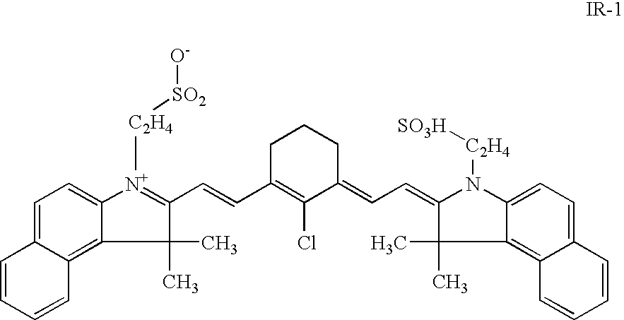
TABLE 7composition of the dry coating(% wt)INGREDIENTS% wtStyrene / acrylonitrile copolymer(1)83Triethylammonium salt of IR-1(2)8Polyacrylic acid binder(3)6Cab O Jet 250(4)3

(1) weight ratio 60 / 40, stabilized with an anionic wetting agent; particle size as defined in Table 8;

(2) infrared absorbi...


PUM

PropertyMeasurementUnit
particle sizeaaaaaaaaaa

Abstract

A method for making a lithographic printing plate is disclosed which comprises the steps of: (i) providing a negative-working, heat-sensitive lithographic printing plate precursor comprising a support having a hydrophilic surface or which is provided with a hydrophilic layer and a coating provided thereon, the coating comprising an image-recording layer which comprises hydrophobic thermoplastic polymer particles and a hydrophilic binder, wherein the hydrophobic thermoplastic polymer particles have an average particle size in the range from 45 nm to 63 nm and wherein the amount of the hydrophobic thermoplastic polymer particles in the image-recording layer is at least 70% by weight relative to the image-recording layer; (ii) exposing the coating to heat or infrared light, thereby inducing coalescence of the thermoplastic polymer particles at exposed areas of the coating; (iii) developing the precursor by applying an aqueous, alkaline solution, thereby removing non-exposed areas of the coating from the support, wherein the aqueous alkaline solution has a pH≧11 and comprises a phosphate buffer or a silicate buffer.

Description

CROSS-REFERENCE TO RELATED PATENT APPLICATIONS [0001] This application claims the benefit of U.S. Provisional Application No. 60 / 587,999 filed Jul. 14, 2004, which is incorporated by reference. In addition, this application claims the benefit of European Application No. 04103247.5 filed Jul. 08, 2004, which is also incorporated by reference.FIELD OF THE INVENTION [0002] The present invention relates to a method for making a negative-working, heat-sensitive lithographic printing plate. BACKGROUND OF THE INVENTION [0003] Lithographic printing presses use a so-called printing master such as a printing plate which is mounted on a cylinder of the printing press. The master carries a lithographic image on its surface and a print is obtained by applying ink to said image and then transferring the ink from the master onto a receiver material, which is typically paper. In conventional, so-called “wet” lithographic printing, ink as well as an aqueous fountain solution (also called dampening l...

Claims


Application Information

Patent Timeline
Patent Type & Authority Applications(United States)
IPC IPC(8): G03F7/00
CPCB41C1/1025B41C2201/02B41C2201/14Y10S430/145B41C2210/06B41C2210/22B41C2210/24B41C2210/04
Inventor VERMEERSCH, JOANMEEUS, PASCALKOKKELENBERG, DIRK
Owner AGFA OFFSET BV
Why Eureka
Try Eureka