
Compression bonding method

Inactive Publication Date: 2006-01-19
KU JA NAM +1
View PDF22 Cites 0 Cited by
  • Summary
  • Abstract
  • Description
  • Claims
  • Application Information

AI Technical Summary

Benefits of technology

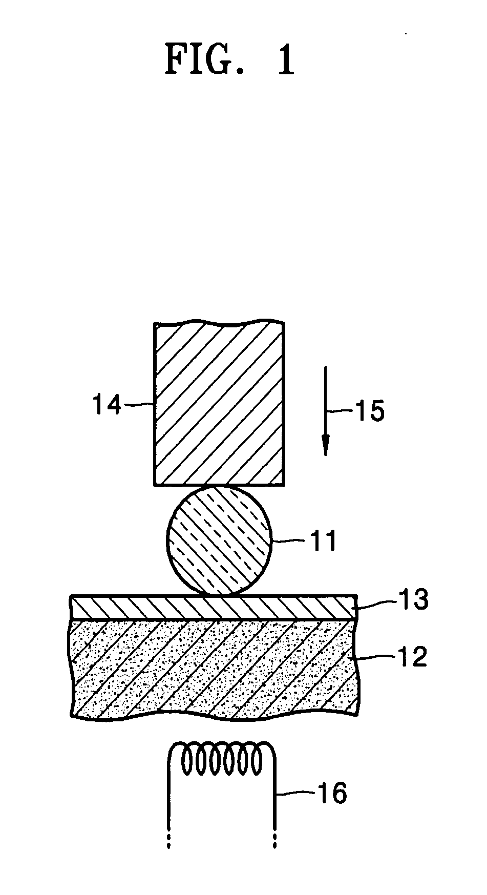
[0012] The present invention provides a compression bonding method through which amorphous glass plates havi

Problems solved by technology

The method using an adhesive is disadvantageous in that it is difficult to finely adjust the quantity of adhesive, it consumes a lot of time, a bonded structure is easy to crack, and bonded elements separate at high humidity.
Moreover, an adhesive may become a source of contamination in optical communication systems or packaging technology, and therefore, a bonding method not using an adhesive is required.
Although a bonding method using a metal has been proposed in this respect, it is not easy to bond glass to a substrate using a metal because the metal and the glass have different material properties.
When the soldering method is used, bonded portions are easily deformed, and poor temperature cycling results appear in package reliability tests.
Moreover, the soldering method has a problem of creep relaxation due to fatigue.
The diffusion method has disadvantages such as necessity of applying an additional electrostatic field, generation of elevated temperature heat, and necessity of using a special chemical mechanism for surface activation.
Such a conventional compression bonding method as described above can be effectively applied to small-sized optical elements such as optical fibers or compact lenses, but it cannot be effectively applied to large-sized optical elements having a flat contact surface.
Although the coefficient of friction of an Al / Si composition needed for bonding is of the order of decimals, a ratio of a length to a thickness of an optical element having a flat surface is actually of the order of hundreds since pressure applied to the optical element is dispersed throughout the flat surface, and thus the coefficient of friction is too large to allow the structure of aluminum to be dissociated at any pressure.
It is difficult to perform this bonding process.
Moreover, even if the bonding process is performed, it is very difficult to strongly bond the optical element to the substrate.

Method used


Image

  • Compression bonding method
  • Compression bonding method
  • Compression bonding method

Examples


first embodiment

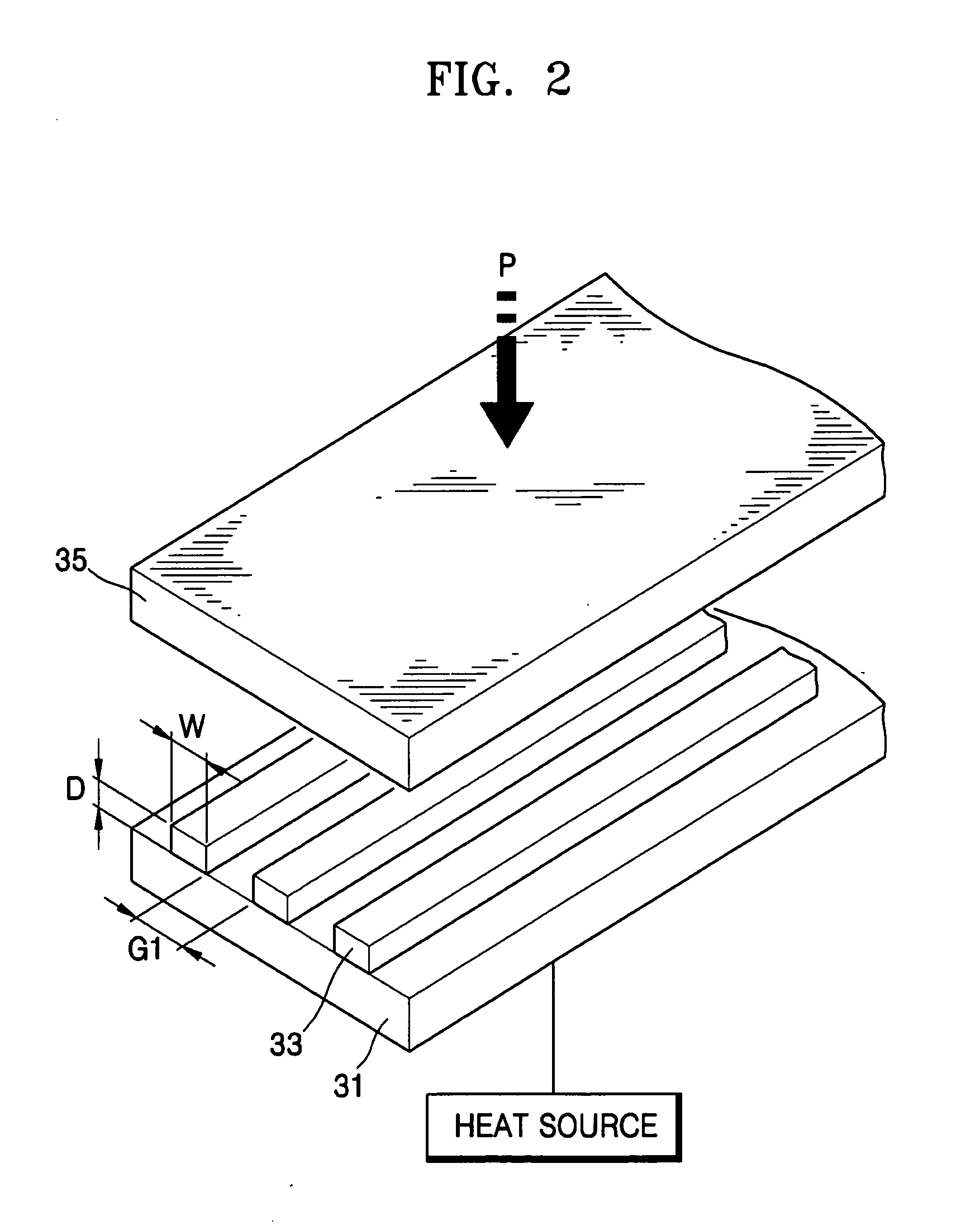
[0029]FIG. 2 shows the arrangement of a substrate, a metal bonding film, and an element to be bonded having a plate shape, which is hereinafter referred to as a bonded element, in a compression bonding method according to the present invention.

[0030] Referring to FIG. 2, a metal bonding film 33 is patterned in stripes on a top surface of a substrate 31, and then a bonded element 35 having a plate shape is disposed above the metal bonding film 33. Next, the substrate 31 is heated, and simultaneously, the metal bonding film 33 is pressed from above. As a result, the metal bonding film 33 is deformed, and therefore, the bonded element 35 is bonded to the substrate 31. Here, a width “w” and a thickness D of the metal bonding film 33 and a gap G1 between the stripes vary with the types of materials of the substrate 31, the metal bonding film 33, and the bonded element 35.

[0031] The substrate 31 may be made of silicon, metal, or ceramic. The metal bonding film 33 may be made of aluminum ...

third embodiment

[0033]FIG. 4 shows the arrangement of a substrate, metal bonding films, and a bonded element having a plate shape in a compression bonding method according to the present invention.

[0034] Similarly to the metal bonding film 33 shown in FIG. 2, a first metal bonding film 53a is patterned in stripes on a top surface of a substrate 51, and then a second metal bonding film 53b is patterned in stripes on a bottom surface of a bonded element 55. The first and second metal bonding films 53a and 53b are heated by heating the substrate 51 and simultaneously applying pressure on a top surface of the bonded element 55, so that the bonded element 55 is bonded to the substrate 51.

[0035] The third embodiment is different from the first embodiment in that the first and second metal bonding films 53a and 53b are respectively formed on the substrate 51 and the bonded element 55.

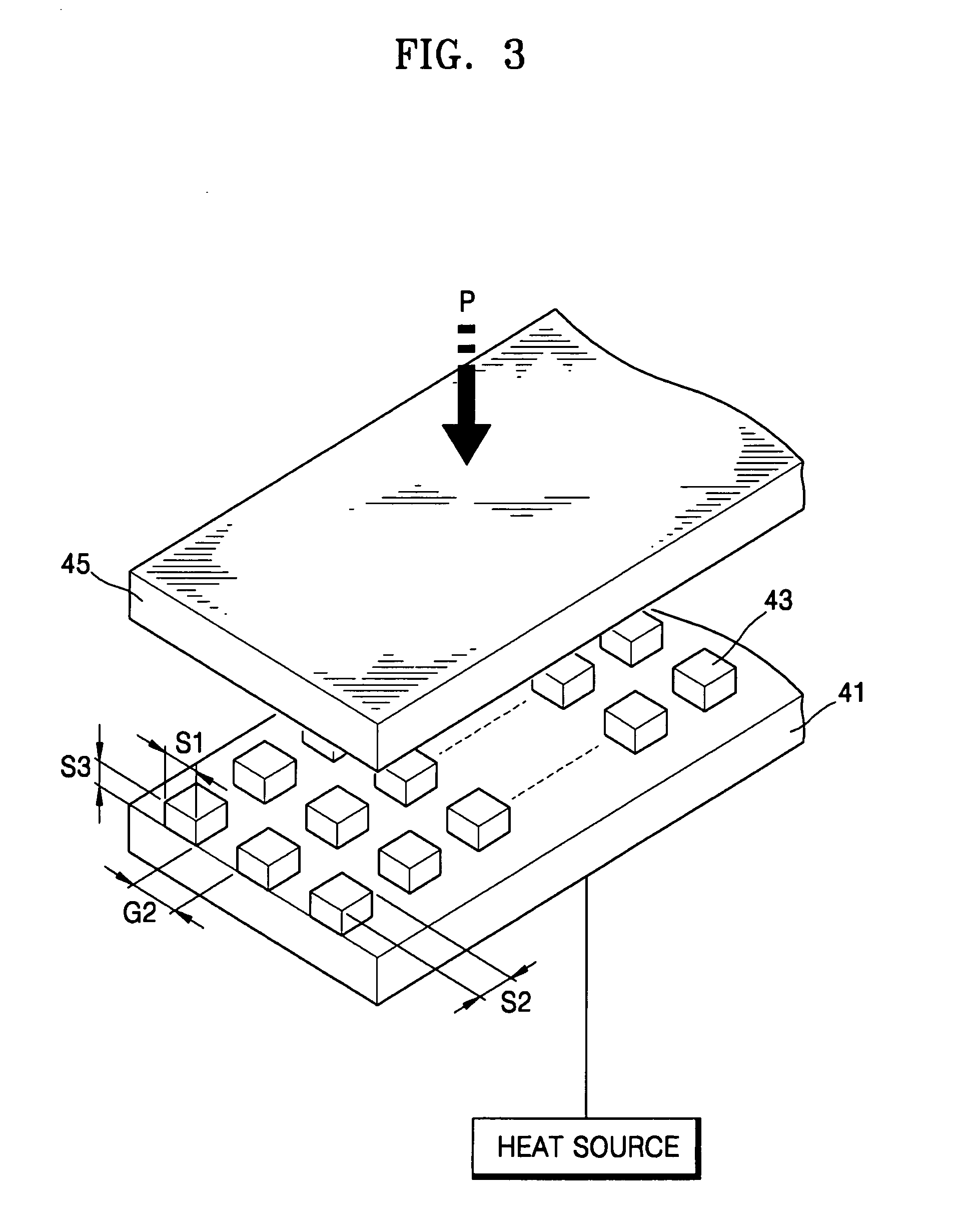
[0036] Other features of the substrates 41 and 51, the metal bonding films 43, 53a, and 53b, and the bonded elements 45 a...


PUM

PropertyMeasurementUnit
Temperatureaaaaaaaaaa
Pressureaaaaaaaaaa

Abstract

A compression bonding method includes patterning a metal bonding film in predetermined shapes on a substrate; and disposing a bonded element above the metal bonding film and applying heat to the substrate and pressure to the bonded element, thereby bonding the bonded element to the substrate having the metal bonding film. Since the compression bonding method allows bonded elements having various shapes and sizes to be bonded to a substrate at a low temperature and pressure, manufacturing is simplified, and the compression bonding method can be applied to various sealing and packaging processes.

Description

CROSS-REFERENCE TO RELATED PATENT APPLICATIONS [0001] This application claims the benefit of Korean Patent Application No. 10-2002-0065843, filed on Oct. 28, 2002, in the Korean Intellectual Property Office, the disclosure of which is incorporated herein in its entirety by reference. BACKGROUND OF THE INVENTION [0002] 1. Field of the Invention [0003] The present invention relates to a compression bonding method, and more particularly, to a method of bonding glass to a substrate using compression bonding at a low temperature and a low pressure. [0004] 2. Description of the Related Art [0005] A method using an adhesive, a soldering method, or a diffusion method can be used to bond glass to a substrate. In the method using an adhesive, glass is bonded to a substrate using an adhesive, such as polymer, plastic, or epoxy. The method using an adhesive is disadvantageous in that it is difficult to finely adjust the quantity of adhesive, it consumes a lot of time, a bonded structure is easy...

Claims


Application Information

Patent Timeline
IPC IPC(8): B23K20/10B23K20/00B23K20/02
CPCB23K20/023B23K20/00
Inventor KU, JA-NAMSERGEY, POTAPOV
Owner KU JA NAM
Learn More