
Doping method, doping apparatus, and control system for doping apparatus

a control system and apparatus technology, applied in the field of ion doping apparatus and a doping method, can solve the problems of inability to detect objective impurity ions, change the amount of impurity ions to be injected, etc., and achieve the effect of high degree of accuracy

Active Publication Date: 2006-01-12
SEMICON ENERGY LAB CO LTD
View PDF27 Cites 8 Cited by
  • Summary
  • Abstract
  • Description
  • Claims
  • Application Information

AI Technical Summary

Benefits of technology

[0015] For solving the above problems, it is an object of the present invention to provide: an ion doping method that allows an ion doping apparatus to adjust the doping amount of ion species with a high degree of accuracy such that the ion doping apparatus not only adjusts the amount of doping when the ratio of ion species changes but also, in particular, correctly measures the ratio of ion species to be injected at lower concentration; a control system for adjusting the doping amount of ion species; and an ion doping apparatus equipped with such a control system.
[0024] In other words, the present invention is a method of conducting a doping treatment by measuring the amount of current of the specific ion with the EXB separator just before the doping treatment and determining the conditions of a subsequent doping treatment. In addition, the present invention is a program to incorporate the results of the measurement into the doping conditions. Furthermore, the present invention is a doping apparatus on which such a program is installed. The concentration of the impurity elements can be made constant using the present invention. Therefore, a stable threshold voltage can be controlled.

Problems solved by technology

Therefore, there is a problem that the amount of impurity ions to be injected changes as the ratio of the respective ions generated in the plasma chamber changes.
However, several problems have been found in the above process comprising the steps of separating each ion, measuring the concentration of the ion from a current value based on each ion to adjust the amount of the doping.
For example, when the amount of the objective ion species such as channel dope is low, the objective impurity ion cannot be detected as the concentration thereof becomes lower than the lower limit of the detectable range.

Method used


Image

  • Doping method, doping apparatus, and control system for doping apparatus
  • Doping method, doping apparatus, and control system for doping apparatus
  • Doping method, doping apparatus, and control system for doping apparatus

Examples


embodiment 1

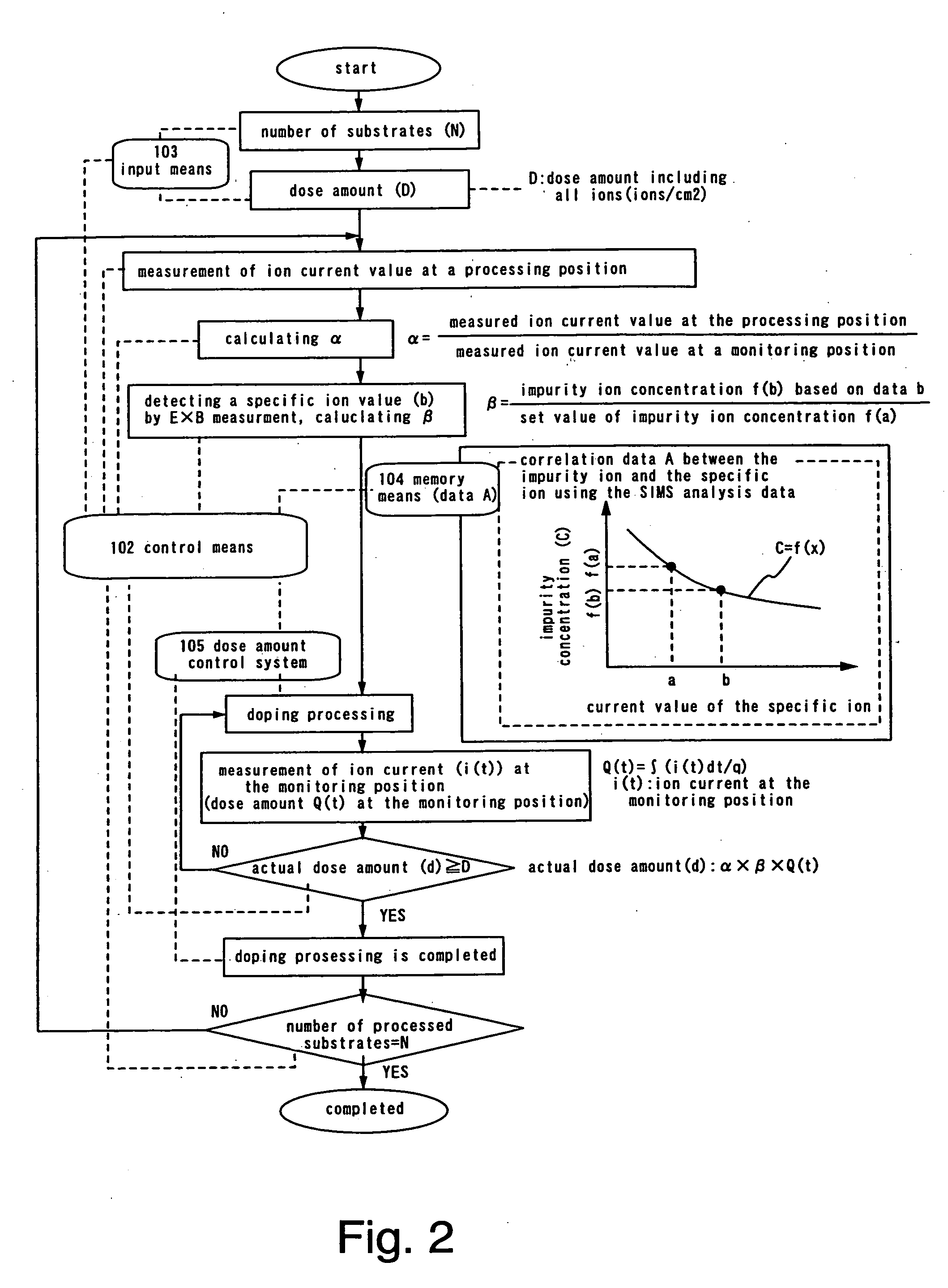
[0044] In a first embodiment of the present invention, we will describe a method for controlling a dose amount in a doing device of the present invention with reference to FIG. 1 and FIG. 2. Here, the present embodiment will describe the case in which low-concentrated boron is injected using 1% B2H6 hydrogen-diluted gas with a very small ion-species ratio.

[0045] The doping apparatus of the present invention comprises a control system constituted of an ion detector 101 that detects the ion current of an ion contained in an ion beam pulled out of an ion source, a control means 102 where a monitor signal measured by the ion detector 101 is entered, an input means 103 for entering set data for setting a desired dose amount into a control means 102, a memory means 104 for storing data (analytical curve) for converting the data measured by the ion detector to the dose amount in advance and entering the convert data into the control means 102, a dose amount control system 105 for receivin...

embodiment 2

[0064] The method for controlling the dose amount is explained using FIG. 4. In Embodiment 2, different from Embodiment 1, the impurity concentration to be injected into the substrate is calculated from the current value of the specific ion obtained by the EXB measurement.

[0065] Here, the steps before obtaining the conversion value (α) are the same as those of Embodiment 1, so that the explanation thereof will be omitted from the following description. However, the dose amount (D′) of only the impurity ions is entered through the input means 103 and is then read and incorporated in the control means 102. In addition, the dose amount at this time is the dose amount of only impurity ions.

[0066] When the conversion value (α) is calculated, the doping processing is initiated. Here, in Embodiment 2, a low-concentrated boron is injected using 1% B2H6 diluted gas with an extremely small ion-species ratio.

[0067] Next, the current value (i(t)) is measured by the EXB measurement. The measu...

embodiment 3

[0078] In Embodiment 3, we will describe one embodiment of the doping apparatus in accordance with the present invention.

[0079] A doping apparatus shown in FIG. 7 comprises an ion source 701, a doping chamber 702 capable of arranging the substrate on the outlet of the ion current thereof, a road lock chamber 703, a waiting chamber 704, and a transport chamber 705. These chambers 702-705 are communicated with gate bulbs. In addition, the transport chamber 705 has a transport means having a double arm and other chambers are equipped with transport means and substrate-holding means (not shown). In addition, an exhaust means 708 allows the doping chamber 702, the transport chamber 705, the waiting chamber 704, and so on become possible of vacuum exhausting. The exhaust means 708 may be an appropriate combination of a dry pump, a mechanical buster pump, a turbo molecular pump, and so on.

[0080] In the doping chamber 702, a substrate is held to perform an ion doping. In the case of proce...


PUM

PropertyMeasurementUnit
currentaaaaaaaaaa
acceleration voltageaaaaaaaaaa
energyaaaaaaaaaa

Abstract

A doping method capable of controlling a dose amount in response to a change the ratio in ion species during a doping process, a control system for controlling a doping amount, and a doping apparatus having a control system are provided. An ion current value of a specific ion in an ion beam is measured. There is an ion detector that measures an ion current value of a specific ion in an ion beam and enters the obtained monitor signal into a control means. Set data for setting a predetermined dose amount is entered into the control means, convert data for obtaining an actual dose amount from the monitor signal is entered into the control means by a memory means. The control means performs data processing on the basis of the input monitor signal and the convert data, a control signal for obtaining the predetermined dose amount is entered from the control means to the dose amount control system to dope the controlled ion beam into the target material.

Description

BACKGROUND OF THE INVENTION [0001] 1. Field of the Invention [0002] The present invention relates to an ion doping apparatus and a doping method using the same, and in particular, a high-precise ion doping technology using impurity regions of source and drain regions of a thin film transistor (TFT), and so on. [0003] 2. Description of the Related Art [0004] The technology for ionizing impurity elements used for the control of valency electrons of a semiconductor and accelerating the ionized electrons in the electric field for injection has been known as an ion injection method. In late years, the doping has been performed by irradiating ions like a shower for injecting impurity elements into a large area substrate of a liquid display device, a light emitting device, or the like. [0005] The ion doping apparatus (hereinafter, also simply referred to as a doping apparatus) is designed such that a doping chamber is communicated with an ion source and is kept under vacuum while placing a...

Claims


Application Information

Patent Timeline
Patent Type & Authority Applications(United States)
IPC IPC(8): C23C16/00H01J37/05H01J37/317H01L21/00H01L21/265
CPCH01J2237/31701Y10S438/918H01L21/67253H01L21/26513H01L21/2658
Inventor NAKAMURA, OSAMU
Owner SEMICON ENERGY LAB CO LTD
Learn More