
Intraocular lens inserter

Inactive Publication Date: 2005-12-22
STRATAS BYRON A
View PDF12 Cites 46 Cited by
  • Summary
  • Abstract
  • Description
  • Claims
  • Application Information

AI Technical Summary

Benefits of technology

[0010] Generally, the present invention is directed to an improved intraocular lens inserter, and in particular to an inserter having a plunger tip that minimizes the risk of damage to the intraocular lens while permitting accurate compression and insertion of the lens. In one embodiment of the invention, an improved lens is also described for use with the improved inserter.
[0017] The IOL is preferably in an uncompressed state within the cartridge, with the lateral diameter of the optic when the IOL is packaged in the cartridge chamber being approximately equal to the cross-sectional diameter of the cartridge chamber. However, the IOL may alternatively be packaged in a partially compressed state, e.g., the IOL may be cupped into a “U” shape. Also, the IOL may be in an uncompressed state until the IOL is to be inserted, and then laterally compressed to reduce the cross-sectional diameter of the IOL, or parts thereof. For example, the cartridge in which the IOL is enclosed may include laterally compressible side walls that press against parts of the IOL when the cartridge is laterally compressed. In a preferred use, the haptic anchor wires are pressed inwardly and over the central part of the haptics by lateral compression of the cartridge, thereby minimizing the risk of damage to the anchor wires.
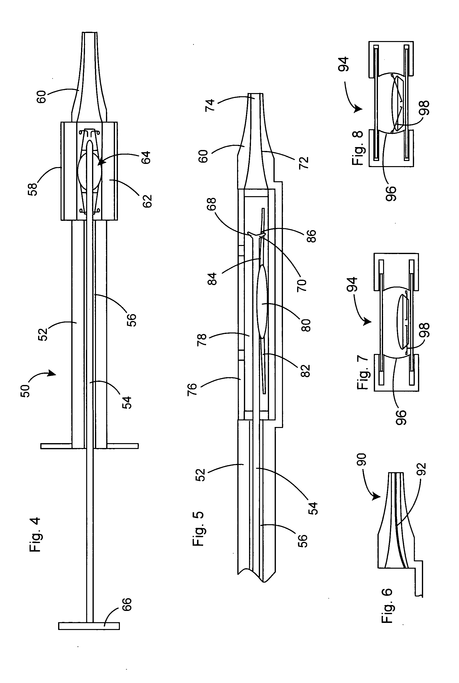
[0021] A discharge nozzle with a tapered bore is positioned on the distal side of the cartridge to receive the IOL. In a preferred embodiment, the discharge nozzle bore includes rifling or grooves to guide the haptics upwardly as the IOL is compressed, thereby aiding in compression, as well as protecting the haptics or parts thereof, such as the haptic anchor wires. These grooves may extend from the proximal to the distal end of the nozzle bore, and may be inclined upwardly to guide the leading haptic edges, or the anchor wires thereon, upwardly as the IOL is pushed forward.

Problems solved by technology

In order to insert the IOL without enlarging the incision, with a resultant increase in trauma and risk of infection, IOLs are constructed of a flexible material, commonly a silicone or acrylic polymeric material that can be laterally compressed to the desired dimension.
Compressible IOLs are necessarily constructed of a soft material that is easily scratched, torn or otherwise damaged.
Moreover, the outwardly extending haptics are susceptible to tearing, twisting or permanent deformation during compression of the IOL.

Method used


Image

  • Intraocular lens inserter
  • Intraocular lens inserter
  • Intraocular lens inserter

Examples


Embodiment Construction

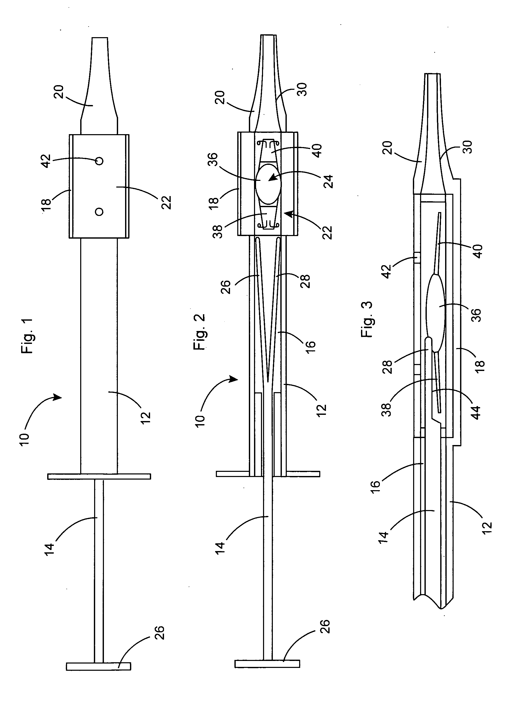
[0037] In the following description, terms such as horizontal, upright, vertical, above, below, beneath, and the like, are used solely for the purpose of clarity in illustrating the invention, and should not be taken as words of limitation. The drawings are for the purpose of illustrating the invention and are not intended to be to scale.

[0038] As best illustrated in FIGS. 1, 2 and 3, inserter, generally 10, is comprised of an elongated handpiece 12 having a proximal end and a distal end. Plunger 14 projects from the proximal end of handpiece 12 and is slidable within a bore 16 within handpiece 12. Cartridge holder 18 is attached to the distal end of handpiece 12, and discharge nozzle 20 is positioned at the distal end of holder 18. Cartridge 22, mounted in holder 18, encloses prepackaged IOL, generally 24.

[0039] Plunger 14 has a proximal end with an enlarged head 26 used by the surgeon to push plunger 14 forward from a retracted position to an inserted position. The distal end of...


PUM


Abstract

An intraocular lens is laterally compressed prior to insertion through an eye incision using an inserter adapted to minimize damage to the intraocular lens. The inserter includes a handpiece with a longitudinal bore, a cartridge holder at the distal end of the handpiece bore, and a discharge nozzle with a tapered bore on the distal side of the cartridge holder. A prepackaged cartridge holding an intraocular lens is mounted in the cartridge holder. The intraocular lens has an optic with leading and trailing haptics axially aligned with the handpiece and nozzle bores. A plunger compresses the lens by moving the lens through the nozzle tapered bore. One plunger described includes flexible distal arms that compress inwardly to maintain the arm tips against the sides of the optic, while another plunger includes an angular tip that engages a hole in the leading haptic to pull the lens through the tapered bore.

Description

BACKGROUND OF THE INVENTION [0001] (1) Field of the Invention [0002] The present invention relates to an intraocular lens insertion instrument and to an intraocular lens, and in particular to an improved inserter and lens permitting accurate lens insertion with minimal risk of damage to the lens. [0003] (2) Description of the Prior Art [0004] During cataract surgery, the defective natural lens is removed by inserting a cutting instrument into the lens through a small (1-4 mm) incision in the ocular tissue of the eye. Ultrasonic vibration of the instrument emulsifies the natural lens into minute particles that are then aspirated from the eye. The natural lens is then replaced with an artificial intraocular lens (IOL), which is inserted through the incision. Some intraocular lenses for refractive correction of an eye are inserted by a similar procedure, but without removal of the natural lens. [0005] An IOL is comprised of a central optic, which serves as the natural lens replacement ...

Claims


Application Information

Patent Timeline
IPC IPC(8): A61F2/16A61F9/00
CPCA61F2/1664
Inventor STRATAS, BYRON A.
Owner STRATAS BYRON A
Learn More