
Method for detecting defects in a piston for an internal combustion engine

A technology for internal combustion engines and pistons, applied in the field of defect measurement devices, can solve problems such as specific detection of defects that hinder small size, complex aperture characteristics of sensors, and defect detection sensitivity

Inactive Publication Date: 2016-08-31
MAHLE INT GMBH
View PDF8 Cites 4 Cited by
  • Summary
  • Abstract
  • Description
  • Claims
  • Application Information

AI Technical Summary

Problems solved by technology

[0004] In the case of the traditional test methods described, it has proven to be a disadvantage that considerable disturbing influences are generally encountered, such as lift-off effects between the sensor and the piston surface, the complex aperture characteristics of the sensor, and the penetration of electromagnetic fields into the piston surface extremely small depth, which hinders the specific detection of small-sized defects
Furthermore, detection is only guaranteed for open defects or defects immediately below the piston surface
In contrast, defects that form even a few tenths of a millimeter below the piston surface are generally hidden from the eddy current sensor
Together with the differential action of the differential probe used, the grain structure of the piston microstructure leads to a microstructural noise enhancement of the eddy current signal, which adversely affects defect detection sensitivity

Method used


Image

  • Method for detecting defects in a piston for an internal combustion engine
  • Method for detecting defects in a piston for an internal combustion engine
  • Method for detecting defects in a piston for an internal combustion engine

Examples


Embodiment Construction

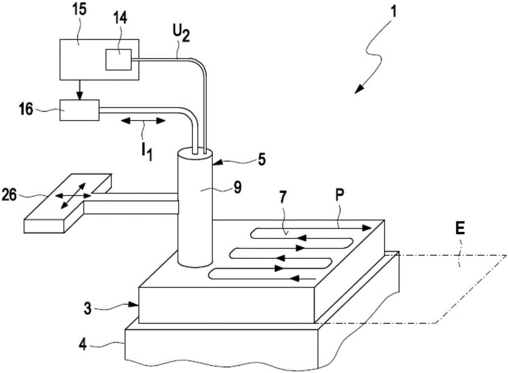
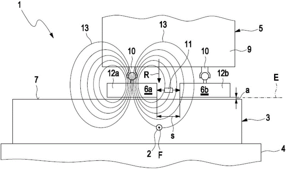
[0035] figure 1 A schematic diagram showing the use according to the invention for detecting the piston 3 in an internal combustion engine - only in figure 1 An example of a measuring device 1 for a defect 2 is shown in highly schematic form in . The measuring device 1 is particularly suitable for carrying out the above-discussed method according to the invention. The measuring device 1 comprises a receiving device 4 for receiving a piston 3 . The receiving device may be in the form of a fixture device, or as figure 1 Formed in the form of a sample stand indicated in high schematic form in middle. The measuring device 1 further comprises a measuring probe 5 which is figure 1 is likewise only highly schematically depicted and accordingly includes a first and a second coil element 6a, 6b for generating and detecting an electromagnetic alternating magnetic field.

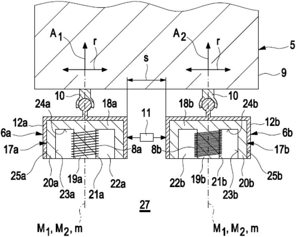
[0036] figure 2 is the area of ​​the measuring probe 5 from the measuring device 1 . It can be seen that the...


PUM


Abstract

A method for detecting defects in a piston for an internal combustion engine may include a) providing the piston (3) in a measurement arrangement (1) that includes a measurement probe (5) having a first electrical coil element (6a) for generating an electromagnetic alternating field and a second electrical coil element for detecting an electromagnetic alternating field. The method may also include b) moving the measurement probe (5) over a piston surface (7) of the piston, and providing an electrical alternating current (I1) in the first coil element (6a) to generate an electromagnetic alternating field (13) that interacts with a material of the piston in the region under the piston surface (7). The method may further include evaluating an electrical alternating voltage (U2) induced in the second coil element (6b) by the electromagnetic alternating field (18) after interaction with the material of the piston (3).

Description

technical field [0001] The invention relates to a method for detecting defects in pistons in internal combustion engines. The invention likewise relates to a measuring device for detecting defects in pistons in internal combustion engines. Background technique [0002] Pistons used as movable components in the combustion chamber of an internal combustion engine are subjected to high mechanical and thermal loads. This makes it almost necessary to produce said pistons without so-called defects, which greatly reduce the wear resistance and service life of the pistons. This applies in particular to the defect occurring in the region of the piston region, known to those skilled in the art as a "piston recess", which axially delimits the combustion chamber of the internal combustion engine in the direction of displacement of the piston. [0003] In the present case, the expression "defect" is to be understood as meaning any kind of crack, hole, break etc. in the material of the ...

Claims


Application Information

Patent Timeline
Patent Type & Authority Applications(China)
IPC IPC(8): G01N27/90
CPCG01N27/9053G01N27/902G01M15/06
Inventor 弗里茨·米歇尔格哈德·穆克约安尼斯·帕帕多普洛斯霍尔格·施内尔
Owner MAHLE INT GMBH
Learn More