
Switching mode power supply

Active Publication Date: 2005-12-22
SEMICON COMPONENTS IND LLC
View PDF3 Cites 36 Cited by
  • Summary
  • Abstract
  • Description
  • Claims
  • Application Information

AI Technical Summary

Benefits of technology

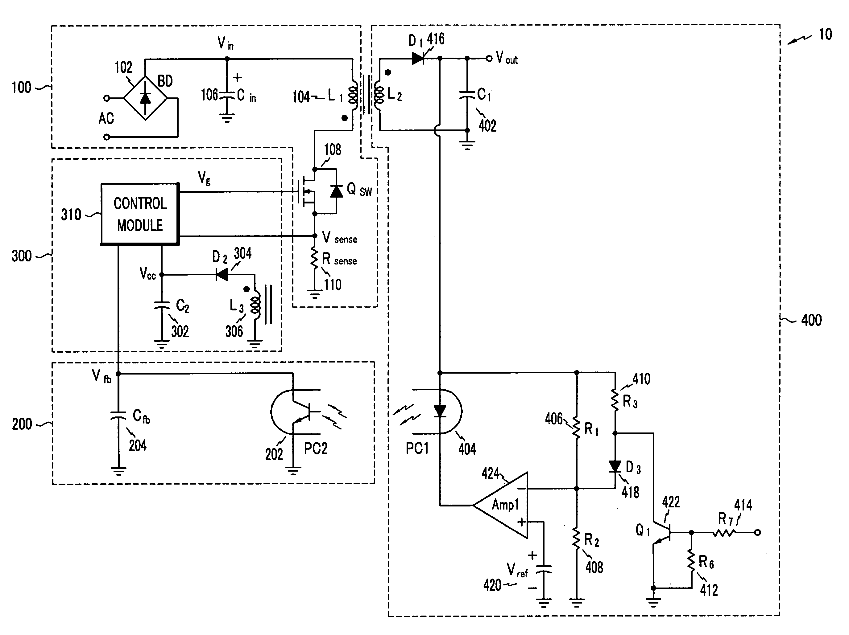
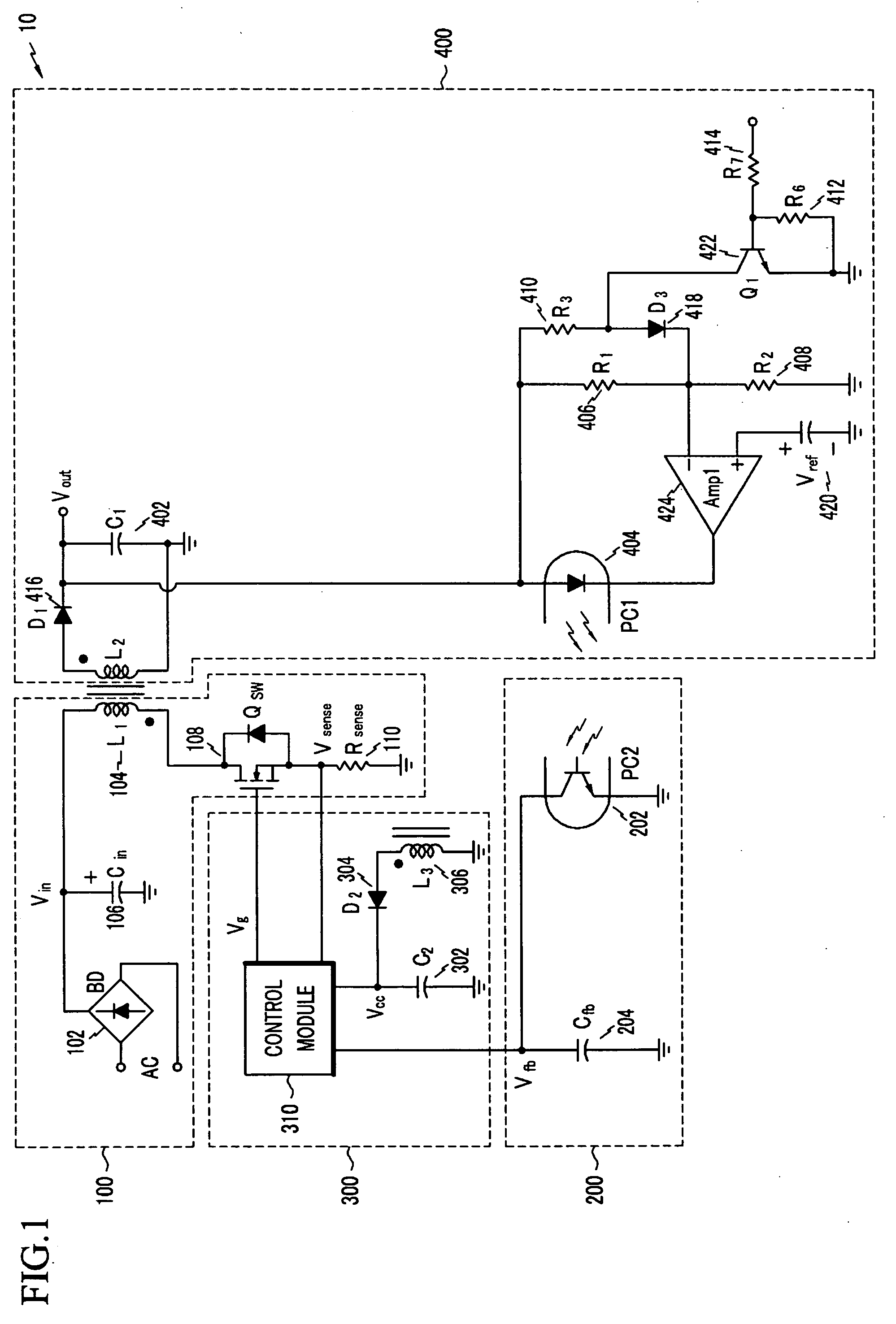
[0012] According to one aspect of the present invention, a switching mode power supply (SMPS) may comprise: a power supply for supplying power to a secondary coil of a transformer according to an operation of a main switch, the main switch being coupled to a primary coil of the transformer; a feedback circuit for generating a feedback voltage corresponding to an output voltage; a control module for stopping the main switch when the feedback voltage is lower than a reference voltage in a standby operation mode; an integrated circuit (IC) power unit for generating a constant voltage, the IC power supply being coupled to the secondary coil of the transformer; and a current generator for using the constant voltage to generate a plurality of constant currents for operating a plurality of ICs, and generating a constant current from among the constant currents when the main switch performs no switching on/off operation.
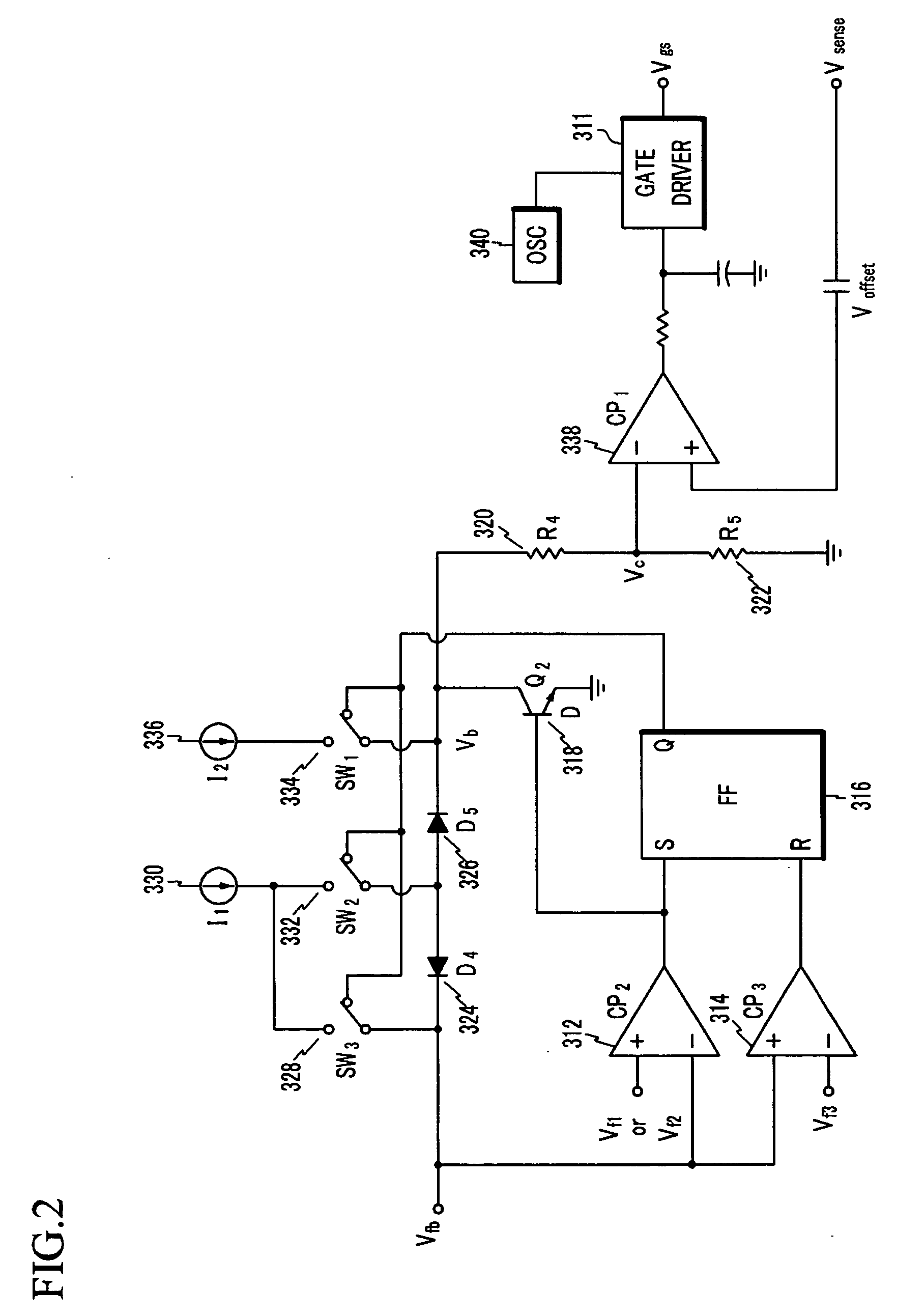
[0013] In one embodiment, a single constant current from a plurality of constant currents may be used to operate an IC which controls the main switch to stop the switching on/off operation. The control module may comprise: a first constant current source for generating the first reference voltage; a second constant current source for generating the second reference voltage; and a current controller for reducing the current of the first constant current source when the main switch performs no switching on/off operation.
[0014] According to another aspect of the present invention, a switching mode power supply may comprise: a power supply for supplying power to a secon

Problems solved by technology

Power electronic devices consume a large amount of power in the normal operation mode, as compared to the standby operation mode.
To reduce power consumption in the standby operation mode, input power to the electronic device is limited.
However, such approaches for entering the standby operation mode are not desirable because they require additional components, thereby resulting in higher production costs.
Moreover, the extent to which power consumption of the electronic device can be decreased is limited because it is likely that an output voltage below a predetermined level for operating the electronic devices may occur.
When using a conventional SMPS in the standby operation mode, a substantial switching loss occurs in the SMPS despite the reduction in power consumption due to a reduced output voltage.
In the standby operation mode, such switching operations consume a considerable amount of power, which prevents greater decreases in power consumption in the standby operation mode.
However, the SMPS having the low power burst mode may have audible noise as the maximum amplitude of current increases.
In addition to the switching loss, the SMPS may also incur conduction loss and core loss.
When a light load is used by the entire system, the switching loss increases relatively, and thus, frequent audible noise is caused and more power is consumed with the increase in the maximum amplitude of current.

Method used


Image

  • Switching mode power supply
  • Switching mode power supply
  • Switching mode power supply

Examples


second embodiment

[0099] A method for solving the problem in which the DC supply voltage VCC is lower than the UVLO voltage in the SMPS including a control module, will now be described. The DC supply voltage VCC functions to generate a plurality of constant current sources for controlling the various IC blocks. It also consumes power for a desired constant current source (used for the burst mode operation) from among the constant current sources at time T2 when the feedback voltage Vfb becomes lower than the second feedback reference voltage Vf2′; that is, when the switching transistor QSW 108 performs no switching on / off operation.

[0100]FIG. 10 is an exemplary conceptual circuit diagram for reducing power consumption of ICs in a like manner of FIG. 1. A control block 500 of FIG. 10 corresponds to the control module 310 of FIG. 1.

[0101] Referring to FIG. 10, the DC supply voltage VCC generates a constant current source Ion for operating ICs including a control block 500, as given in Equation 3. E...

first embodiment

[0116] The current of the constant current source I3 358 is reduced by using the current mirrors in FIG. 13, and it is also possible to reduce power consumption of ICs by using the current mirrors and reducing the current of the constant current source I3 358 in the standby operation mode in the first embodiment shown in FIG. 1.

[0117] As described herein, the control module 310 according to embodiments of the present invention delimits a maximum amplitude of current below a predetermined level by using an automatic burst operation mode and a current operation mode, thereby preventing occurrence of audible noise. In particular, it is possible to design the internal circuit more simply and reduce power consumption required for conversion from the burst mode into the normal operation mode by controlling the switching transistor according to two sense levels (e.g., the first feedback reference voltage and the second feedback reference voltage). Power consumption is further reduced by co...


PUM


Abstract

In one embodiment, a switching mode power supply (SMPS) may comprise: a power supply for supplying power to a secondary coil of a transformer according to an operation of a main switch, the main switch being coupled to a primary coil of the transformer; a feedback circuit for generating a feedback voltage corresponding to an output voltage; a control module for stopping the main switch when the feedback voltage is lower than a reference voltage in a standby operation mode; an integrated circuit (IC) power unit for generating a constant voltage, the IC power supply being coupled to the secondary coil of the transformer; and a current generator for using the constant voltage to generate a plurality of constant currents for operating a plurality of ICs, and generating a constant current from among the constant currents when the main switch performs no switching on / off operation.

Description

CROSS REFERENCE TO RELATED APPLICATION [0001] This application claims priority to and the benefit of Korea Patent Application No. 10-2004-44481 filed on Jun. 16, 2004 in the Korean Intellectual Property Office, the entire content of which is incorporated herein by reference. BACKGROUND OF THE INVENTION [0002] (a) Field of the Invention [0003] The present invention relates to a switching mode power supply (SMPS). More specifically, the present invention relates to a switching mode power supply for reducing power consumption in the standby operation mode. [0004] (b) Description of the Related Art [0005] In general, a switching mode power supply (SMPS) converts a direct current (DC) supply voltage into one or more DC output voltages that have a greater or lesser magnitude than the DC supply voltage. SMPSs are widely used in power electronic devices, particularly battery-powered devices such as portable cellular phones and laptop computers. Typically, SMPSs have a normal operation mode ...

Claims


Application Information

Patent Timeline
IPC IPC(8): H02M3/28H02M3/335
CPCH02M3/33523H02M3/33507H02M3/28
Inventor CHOI, JIN-HORYU, YOUNG-CHULHUH, DONG-YOUNG
Owner SEMICON COMPONENTS IND LLC
Learn More