
Carbon dioxide-based bi-level CPAP control

a carbon dioxide and control technology, applied in mechanical equipment, valves, respirators, etc., can solve the problems of difficult measurement accuracy, response time, and discomfort of patients exhaling

Inactive Publication Date: 2005-12-22
INVACARE CORP
View PDF101 Cites 60 Cited by
  • Summary
  • Abstract
  • Description
  • Claims
  • Application Information

AI Technical Summary

Benefits of technology

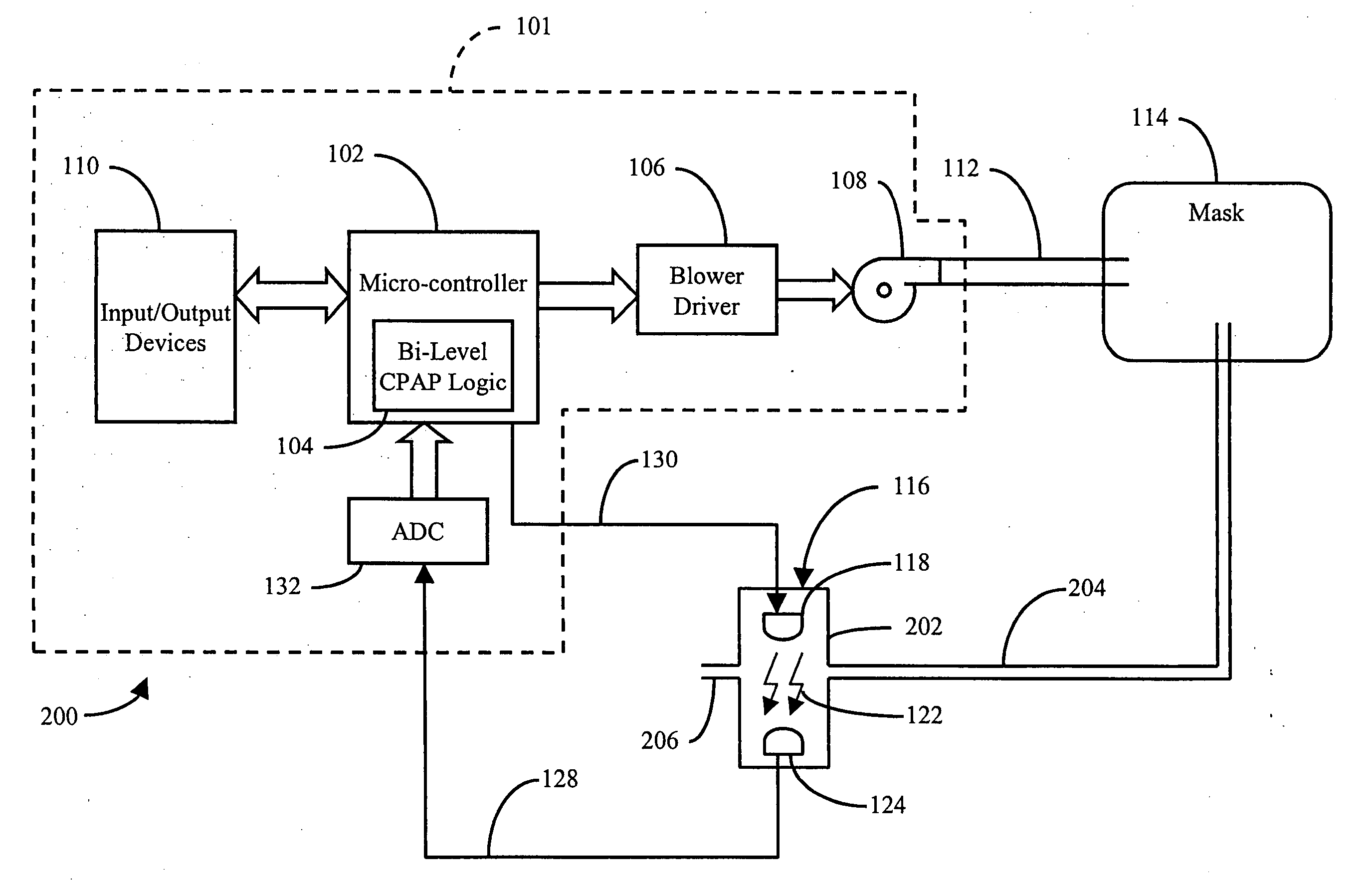
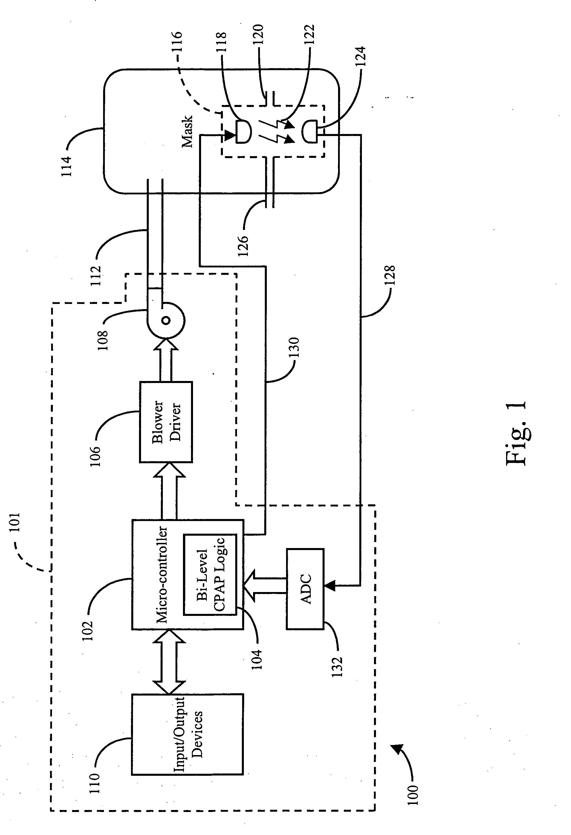
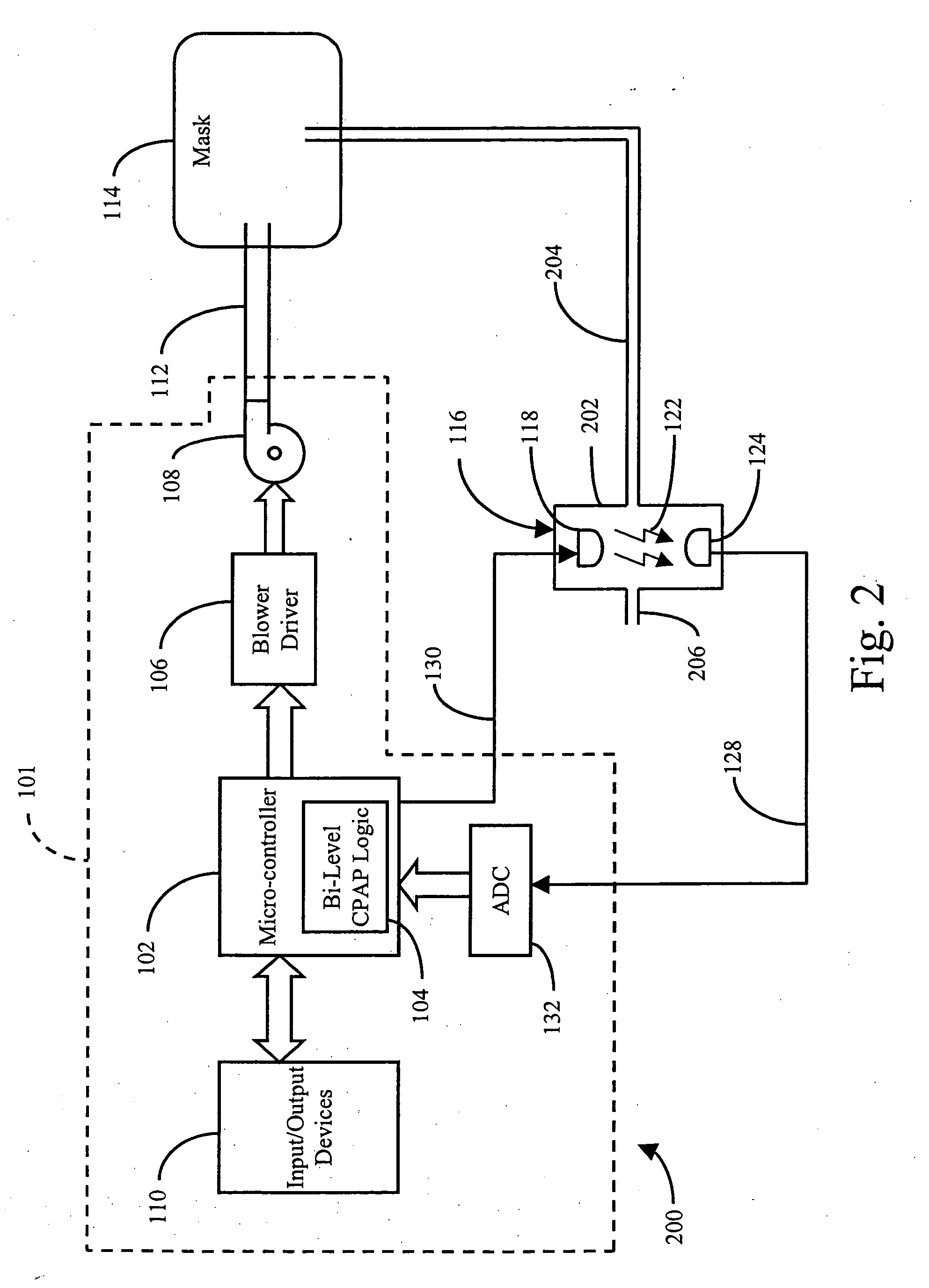
[0007] According to one embodiment of the present invention, a carbon-dioxide sensor is used to determine whether a patient undergoing bi-level CPAP treatment for obstructive sleep apnea is inhaling or exhaling. The carbon-dioxide sensor uses infrared light to determine the presence or absence of carbon-dioxide in a patient breathing interface such as, for example, a nasal and mouth mask, worn by the patient. In this regard, the carbon-dioxide sensor includes, for example, an infrared light emitter and detector separated by an air gap. Patient exhalation results in carbon-dioxide being present in the air gap. This causes less infrared light to be transmitted to the detector due to the carbon-dioxide absorbing a portion of the infrared light. Conversely, patient inhalation results in little or no carbon-dioxide being present in the air gap. This causes more infrared light to be transmitted to the detector because there is little or no carbon-dioxide present to absorb the infrared light. Through such detection, the logic of the present invention coordinates the IPAP and EPAP levels to provide the patient with a comfortable bi-level CPAP regimen.
[0010] It is therefore an object of the present invention to provide a system and method of providing a higher positive airway pressure breathing gas during patient inhalation and a lower positive airway pressure breathing gas during patient exhalation.

Problems solved by technology

While such a regimen is successful in treating obstructive sleep apnea, some patients experience discomfort when exhaling because of the level of positive air pressure being delivered to their airways during exhalation.
However, using the instantaneous and average flow rates of the air being delivered to the patient has several disadvantages including accuracy and response time.
In this regard, the flow of air is generally turbulent and therefore difficult to measure accurately.
Additionally, leakages caused by loose fitting patient breathing interfaces such as, for example, nasal and mouth masks, contribute to the difficulty of determining accurate air flow rates.
Closely connected thereto, the turbulent flow and difficulty of accurate measurement necessarily cause a slow response time in changing between IPAP and EPAP levels.

Method used


Image

  • Carbon dioxide-based bi-level CPAP control
  • Carbon dioxide-based bi-level CPAP control
  • Carbon dioxide-based bi-level CPAP control

Examples


Embodiment Construction

[0021] Illustrated in FIG. 1 is a first bi-level CPAP system 100 of the present invention. The system has a bi-level CPAP apparatus 101 and a patient breathing interface 114. The bi-level CPAP apparatus 101 has a micro-controller 102 with associated bi-level CPAP logic 104. The micro-controller 102 interfaces with a plurality of components including input / output devices 110, analog-to-digital converter (ADC) 132, and blower driver 106. Input / Output devices 110 include, for example, controls that allow a clinician or doctor to set the IPAP and EPAP levels in micro-controller 102 and in bi-level CPAP logic 104. Blower driver 106 interfaces with and drives blower 108 through a range of variable speeds that result in a range of variable air pressures that define the IPAP and EPAP levels. The blower 108 preferably has a motor and a fan and is driven by a pulse-width modulated (PWM) signal wherein the pulse width or duty cycle defines the variable speed and pressure of the blower. Alterna...


PUM


Abstract

A system and method of providing bi-level CPAP therapy is provided that incorporates an infrared carbon-dioxide sensor to determine whether a patient is inhaling or exhaling. Patient exhalation causes the infrared light to be absorbed, while patient inhalation reduces the presence of carbon-dioxide causes little or no absorption of carbon-dioxide The level of carbon-dioxide in an associated patient breathing interface is monitored for thresholds that trigger higher CPAP pressure upon inhalation and lower CPAP pressure upon exhalation.

Description

CROSS-REFERENCE TO RELATED APPLICATIONS [0001] This patent application is related to provisional application Ser. No. 60 / 236,123, titled “Carbon Dioxide-Based Bi-Level CPAP Control,” which is hereby fully incorporated by reference.FIELD OF THE INVENTION [0002] The invention relates generally to the administration of constant positive airway pressure (CPAP) to treat obstructive sleep apnea, and more particularly, to methods and apparatuses for administering a higher CPAP upon inhalation and a lower CPAP upon exhalation. BACKGROUND OF THE INVENTION [0003] Obstructive sleep apnea is an airway breathing disorder caused by relaxation of the muscles of the upper airway to the point where the upper airway collapses or becomes obstructed by these same muscles. It is known that obstructive sleep apnea can be treated through the application of pressurized air to the nasal passages of a patient. The application of pressurized air forms a pneumatic splint in the upper airway of the patient ther...

Claims


Application Information

Patent Timeline
Patent Type & Authority Applications(United States)
IPC IPC(8): A61M16/00A61M16/16
CPCA61M16/00A61M2205/3368A61M16/161A61M16/0069A61M2230/432A61M16/085A61M16/024
Inventor RICHEY, JOSEPH B. II
Owner INVACARE CORP
Learn More