
Electronic circuit for a weight-in-motion sensor

a technology of electronic circuit and sensor, which is applied in the direction of weighing apparatus, electric variable regulation, amplifiers, etc., can solve the problems of high cost, high cost of highly insulating cables, and increase the cost of the system accordingly, so as to achieve less complex, less susceptible to damage, and cost-effective

Inactive Publication Date: 2015-02-12
KISTLER HLDG AG
View PDF4 Cites 7 Cited by
  • Summary
  • Abstract
  • Description
  • Claims
  • Application Information

AI Technical Summary

Benefits of technology

The invention is a circuit that can be connected to a two-core cable, which allows for transmitting signal data and power supply. This means that no additional components need to be exchanged, eliminating the need to block off roads. The transmission of voltage signals is easier than that of charges, so a simpler and more cost-effective cable can be used. Additionally, the cable is less prone to damage and can also be used for power supply. The required signal processing in the cabinet is also simpler compared to a charge amplifier.

Problems solved by technology

This results in high costs because the highly insulating cables are very expensive.
Long cables are frequently required in this application because the cabinet containing the electronics may be located far from the sensor in the road such that the costs of the system increase accordingly.
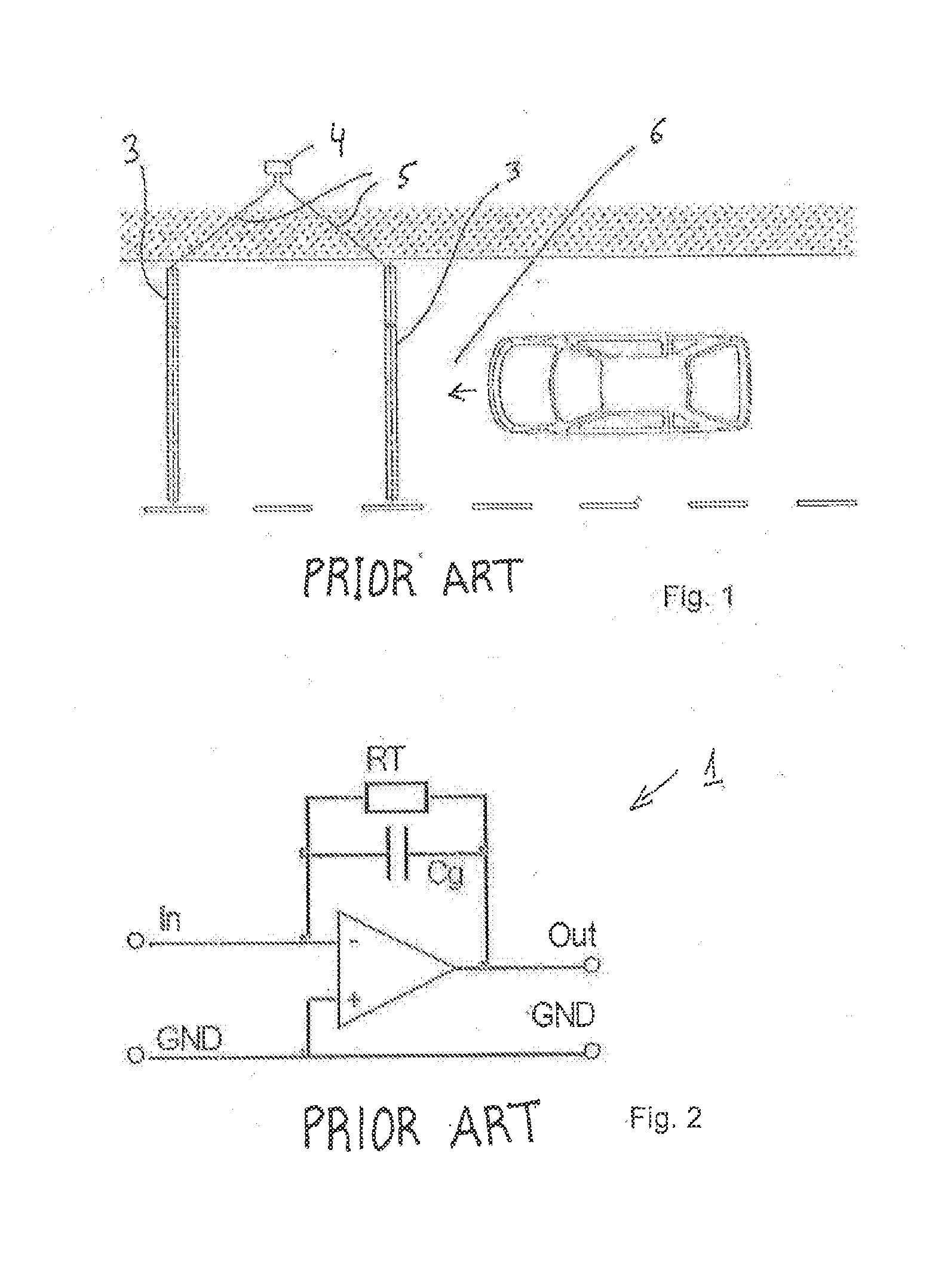
The highly insulating connecting cable 5 from the sensor 3 to the charge amplifier 1 is very expensive and requires a very clean installation in order to prevent the cable 5 from being soiled and thereby compromising the required high insulation.
Since the electronics are installed in the roadway together with the sensor in the described application of WIM sensors, a malfunction must be prevented in all circumstances because the sensor cannot be readily replaced.
In this case, the roadway is impassable for a certain period of time and needs to be blocked off.
The sensitivity of the signal respectively changes due to the high capacitance of the sensor and due to the change of this capacitance during temperature fluctuations such that the measuring results become less accurate.
However, since the sensor ground needs to have the same potential as the output signal ground in a WIM sensor, this circuit cannot be used for the described purposes.
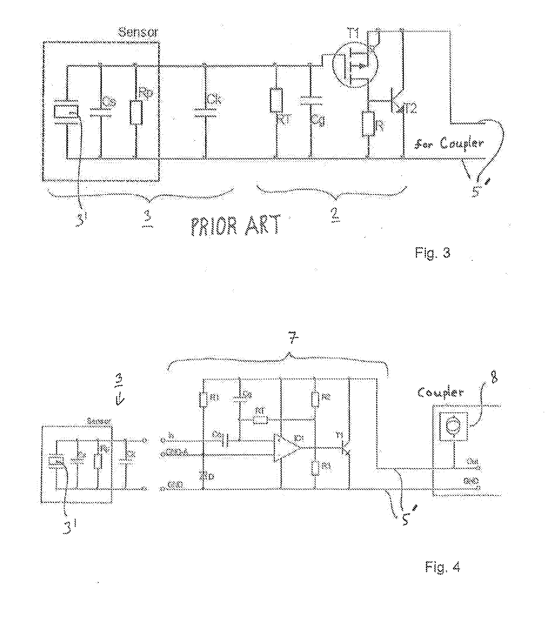
In a WIM, the sensor capacitance Cs is high and, in particular, not stable over the service life due to temperature influences, manufacturing tolerances and other environmental influences.
This massively affects the sensitivity of the measuring chain and practically makes it impossible to carry out an exact measurement.
Nevertheless, an IEPE circuit cannot be used in the described application because the high capacitance and the internal resistance of the sensor are direct components of the circuit.
In addition, the resistance of each sensor changes over time such that the sensitivity of the signal also changes over time.
An IEPE circuit consequently does not make it possible to obtain measuring results that have the required accuracy, particularly over a prolonged period of time.
However, a shielded two-core cable, which may be very long and therefore very expensive as described above, is required for the signal transmission and the power supply in this case.
Consequently, this is not the desired solution.
If the charge amplifier is directly installed into the sensor, an additional cable is required for the power supply such that the costs of the system are increased again.

Method used


Image

  • Electronic circuit for a weight-in-motion sensor
  • Electronic circuit for a weight-in-motion sensor
  • Electronic circuit for a weight-in-motion sensor

Examples


Embodiment Construction

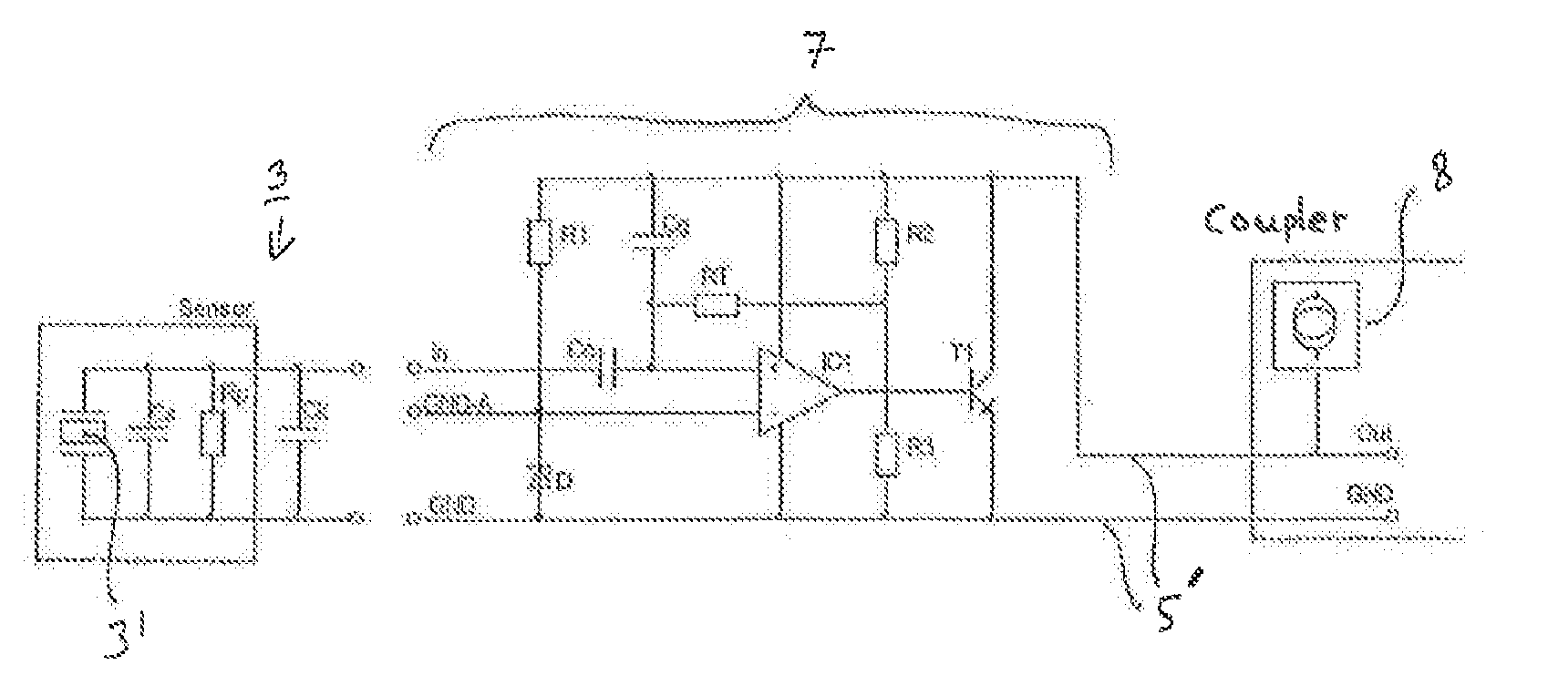
[0034]FIG. 4 shows the inventive electronic circuit 7 that is insensitive with respect to the varying sensitivity caused by the capacitance changes of the sensors 3.

[0035]The components IC1 (integrated circuit) and T1 (impedance converter) form the active amplifier stage. The Zener diode D defines the initial quiescent value or the bias voltage in conjunction with the resistors R2 and R3. The sensitivity of the measuring chain can be adjusted with the capacitance Cg. In addition, the resistor RT forms the time constant of the measuring signal in conjunction with the resistors R2, R3 and the capacitance Cg. The capacitor Cc serves for decoupling the voltage across the Zener diode D from the sensor 3.

[0036]The entire circuit 7 is supplied with power by a power source 8 that is accommodated in a so-called coupler (coupler).

[0037]The inventive circuit according to FIG. 4 combines the advantages of both systems: the sensitivity is nearly independent of the input capacitance analogous to ...


PUM


Abstract

An electronic circuit that changes a charge signal into a voltage signal within a sensor suitable for direct installation in a roadway can be connected to two single-core cables that need not be highly insulating yet can realize the required power supply of the electronics. The circuit includes an integrated impedance converter (IEPE) at the output to a two-core cable and a charge amplifier with an IC1 that has two inputs. A capacitor Cc is connected in series to the signal output of the sensor at one input of the IC1. A Zener diode D is arranged between the ground output of the sensor and the second input of the IC1 and can be supplied with power by a resistor R1 in conjunction with a power supply arranged on the output side in order to adapt the potential at the second input of the IC1.

Description

CROSS-REFERENCE TO RELATED APPLICATIONS[0001]This application claims priority to International Application Serial No. PCT / CH2013 / 000051, filed Mar. 26, 2013, which claims priority to Swiss Application No. 00424 / 12 filed Mar. 26, 2012. International Application Serial No. PCT / CH2013 / 000051 is hereby incorporated herein for all purposes by this reference.FIELD OF THE INVENTION[0002]The invention pertains to an electronic circuit for converting a charge signal of a WIM (Weigh-In-Motion) sensor installed in a roadway into a voltage signal, as well as to a sensor that comprises such a circuit.BACKGROUND[0003]Force sensors for determining the weight of vehicles on the road while they travel over these sensors, namely so-called WIM (Weigh-In-Motion) sensors, are installed in a roadway such as, for example, a road and measure the dynamic ground reaction forces of the vehicles in order to determine their weight based on these forces. Piezoelectric sensors are typically used for this purpose....

Claims


Application Information

Patent Timeline
Patent Type & Authority Applications(United States)
IPC IPC(8): G05F5/00
CPCG05F5/00G01D3/036G01D18/004G01G3/13G01G19/024G01L1/16H03F3/347H03F3/70
Inventor CORNU, DAVIDHOFMANN, ADRIANAMSTUTZ, LEOSTREBEL, ROMANCAVALLONI, CLAUDIO
Owner KISTLER HLDG AG
Learn More