
Magnetic film for magnetic device

a magnetic device and film technology, applied in the field of magnetic film for magnetic devices, can solve the problems of insufficient magnetic field of permalloy poles, difficult to machine magnetic poles for small heads, and small saturation magnetization of ni—zn ferrite, and achieve the effect of greater saturation magnetization of film and high recording density

Inactive Publication Date: 2005-12-08
FUJITSU LTD
View PDF16 Cites 7 Cited by
  • Summary
  • Abstract
  • Description
  • Claims
  • Application Information

AI Technical Summary

Benefits of technology

The present invention provides a magnetic film with a higher saturation magnetization than conventional films. This results in a magnetic head or solid device that can record data with high recording density.

Problems solved by technology

The technical problem addressed in this patent is the need for a magnetic film with a high saturation magnetization property for use in a hard disk drive unit and a solid device. The current materials used for magnetic poles, such as Ni—Zn ferrite and Fe—Al—Si alloy, have limitations in their saturation magnetization. The invention proposes a new magnetic film that can overcome these limitations and improve recording density.

Method used


Image

  • Magnetic film for magnetic device
  • Magnetic film for magnetic device
  • Magnetic film for magnetic device

Examples


Embodiment Construction

[0030] Preferred embodiments of the present invention will now be described in detail with reference to the accompanying drawings. The embodiments are the magnetic film for a magnetic device, the magnetic head for a hard disk drive unit and a solid device having the magnetic film.

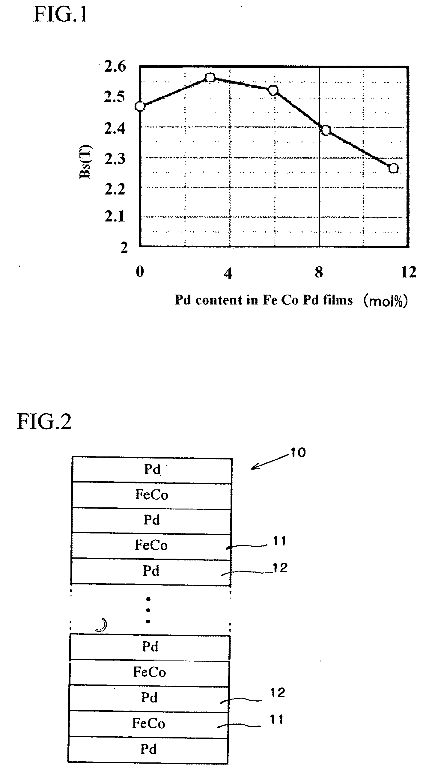
[0031] Firstly, a relationship between amount of Pd added to Fe70CO30 alloys and saturation magnetization of spattered magnetic films will be explained with reference to FIG. 1. In the experiment, a plurality of targets made of Fe70Co30 alloy, to each of which Pd was added, were prepared. Amount of Pd included in the targets were different. The spattering was performed under the conditions of 1000 W and 0.4 Pa. Thickness of the spattered films were 50 nm. Measured saturation magnetization (Bs) of the spattered films are shown in FIG. 1. Note that, the spattered film(s) will be sometimes called “first magnetic film(s)”. According to FIG. 1, the saturation magnetization (Bs) of the spattered film including n...


PUM


Abstract

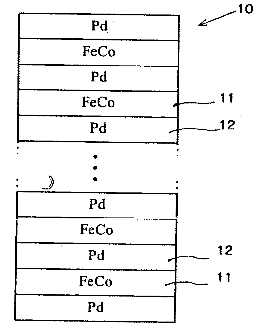
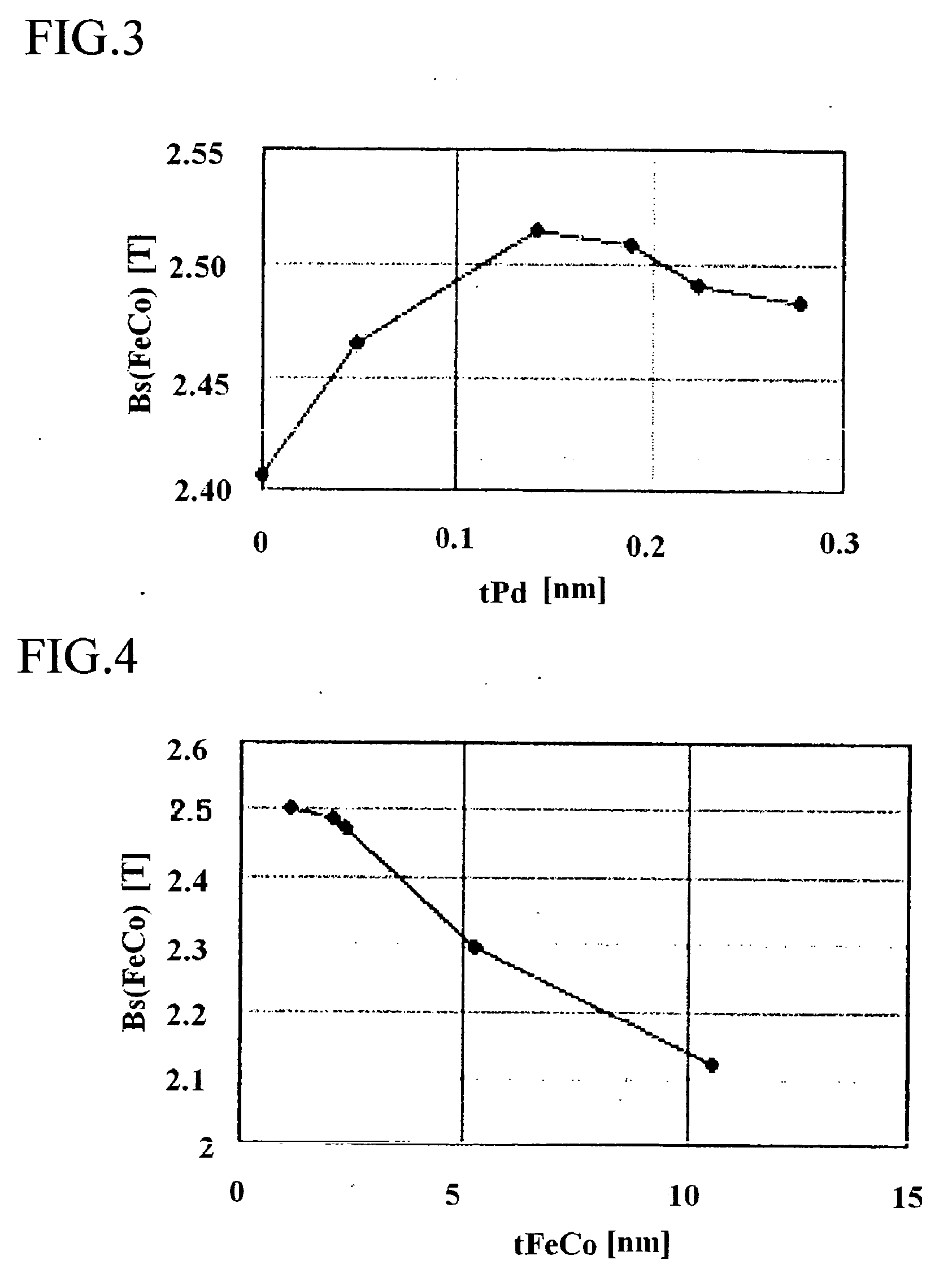
The magnetic film of a magnetic device can be practically used and can have saturation magnetization greater than 2.45T. The magnetic film is an alloy film consisting of iron, cobalt and palladium. Molar content of palladium is 1-7%, and the alloy film is formed by a spattering method. Another magnetic film comprises a ferromagnetic film, and a palladium film or an alloy film including palladium, which are alternately layered. Thickness of the palladium film or the alloy film including palladium is 0.05-0.28 nm, and the layered films are formed by a spattering method or a evaporation method.

Description


Claims


Application Information

Patent Timeline
Owner FUJITSU LTD
Learn More