Planar light source and light guide for use therein

a light guide and light source technology, applied in the direction of planar/plate-like light guides, lighting and heating apparatus, instruments, etc., can solve the problems of easy drop in luminance of the portion or the region, inability to eliminate the above-described dark part in the backlight using a spot-like light source, and difficulty in achieving both power consumption reduction and maintenance of luminance uniformity, etc., to achieve high uniformity and avoid any variation in luminance

Inactive Publication Date: 2005-11-17
MITSUBISHI CHEM CORP
View PDF3 Cites 49 Cited by
  • Summary
  • Abstract
  • Description
  • Claims
  • Application Information

AI Technical Summary

Benefits of technology

[0013] According to-the above-described present invention, there can be provided a high quality planar light source device having a high unif

Problems solved by technology

However, this groove has a symmetric cross section, the light is uniformly diffused on opposite sides, and therefore the dark part formed in a specific region of the light guide, for example, a corner portion cannot be sufficiently eliminated.
As described above, it has been difficult to realize both reduction of power consumption and maintenance of uniformity of luminance in the conventional backlight using the spot-like light source as the primary light source.
Moreover, even in the backlight using a linear light source such as a cold cathode tube as the primary light source, there has been a problem that a sufficient quantity of light does not

Method used


Image

  • Planar light source and light guide for use therein
  • Planar light source and light guide for use therein
  • Planar light source and light guide for use therein

Examples


example 1

Preparation of Light Guide

[0060] A transfer pattern for forming a light guide surface structure was cut on a mirror-finished surface of a brass plate having an outer shape dimension of 48 mm×34 mm and a thickness of 3 mm at an effective region having a dimension of 40 mm30 mm to obtain a mold. In the surface structure, circular elongated prisms were concentrically formed centering on the vicinity of one corner portion in parallel to each other centering on the vicinity of one corner portion of rectangular outer shape having a dimension of 48 mm×34 mm, each having a cross-sectional shape of an isosceles triangle having an apex angle of 160 degrees and a bottom side dimension of 30 μm, and flat portions each having a width of 30 to 200 μm was formed between adjacent circular arc elongated prisms in such a manner that an interval was gradually narrowed from a central portion. Injection forming was performed using the above obtained mold and a mold formed of the brass plate having the...


PUM


Abstract

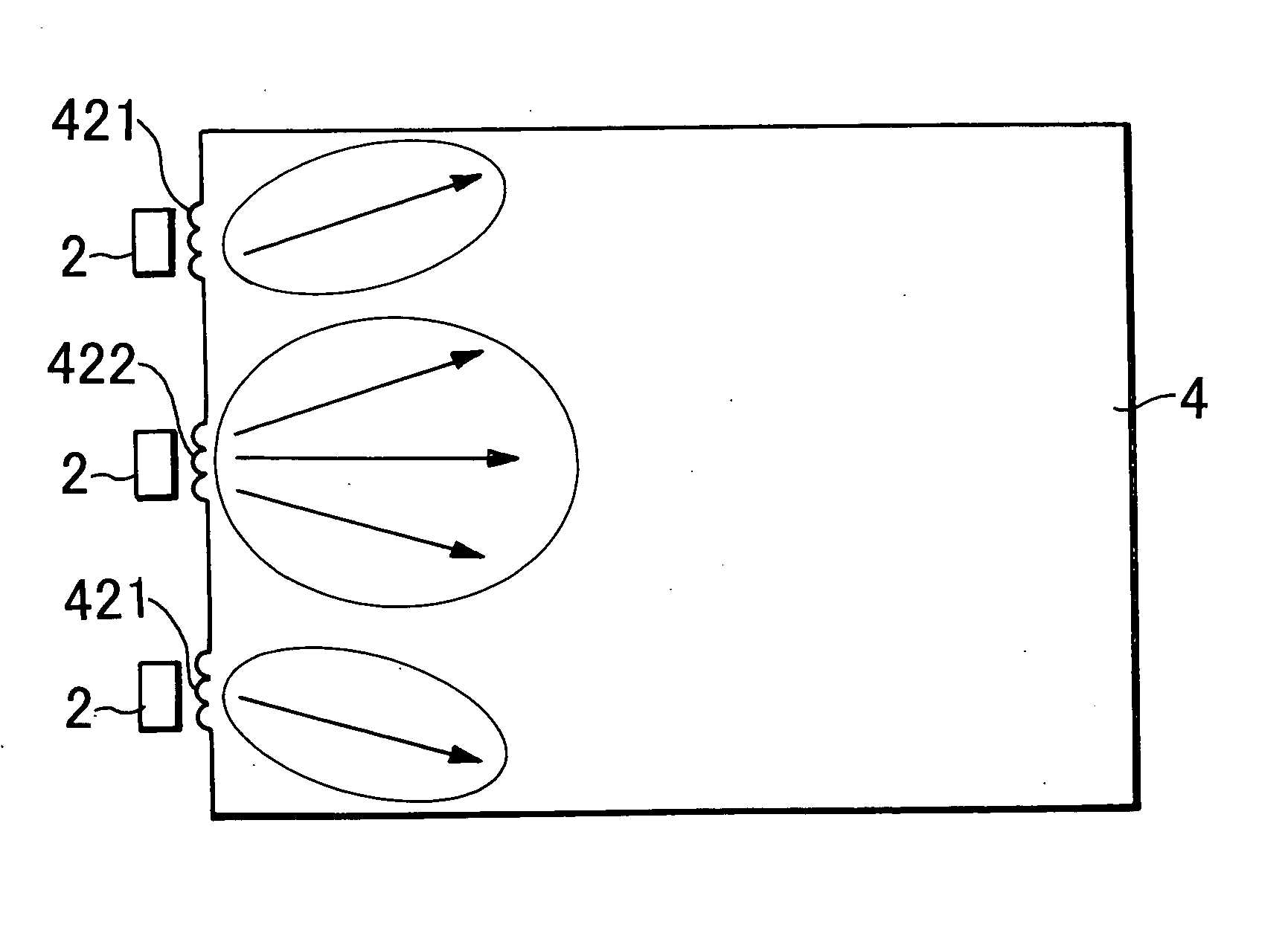
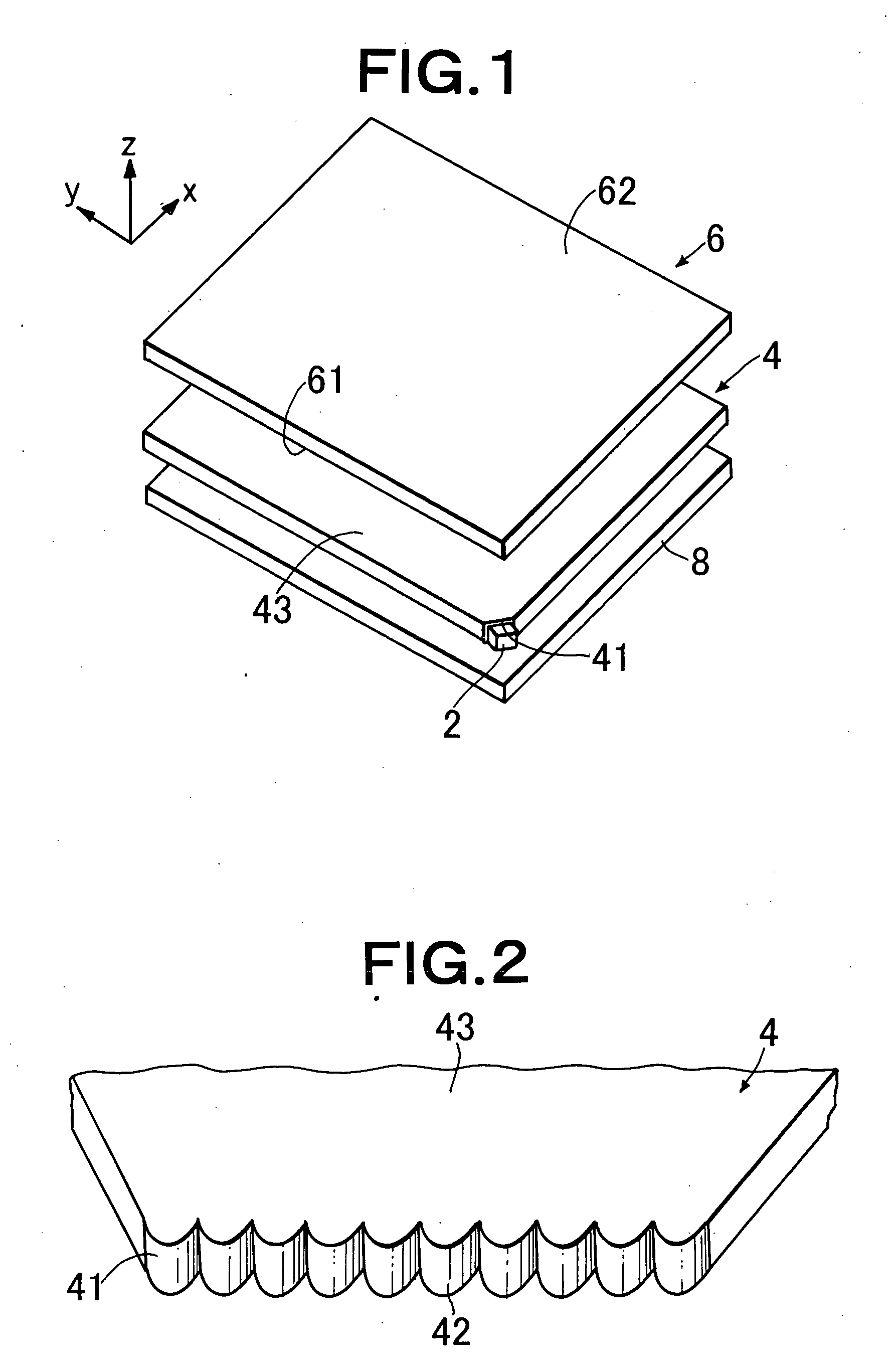
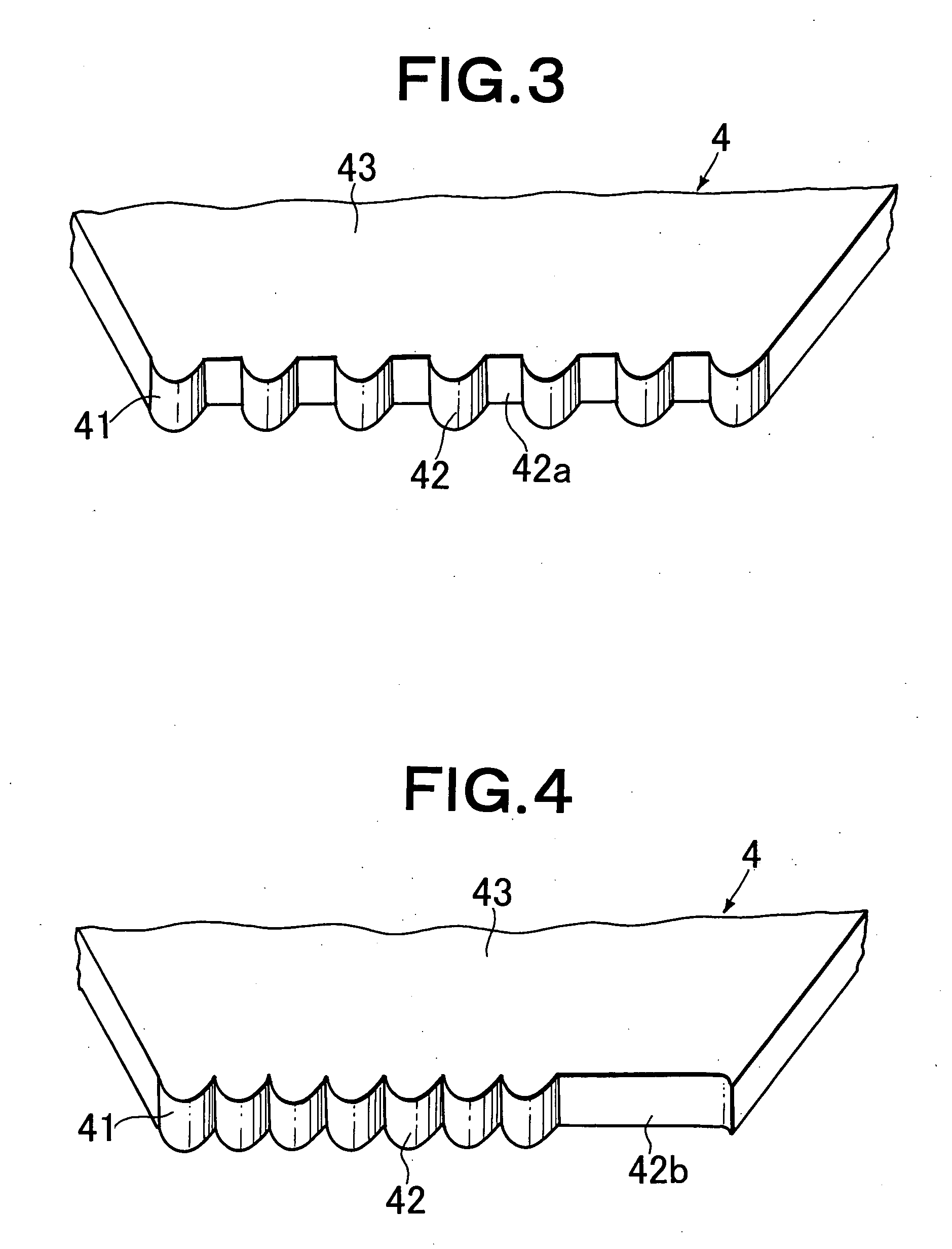
A planar light guide (4) having a light entrance end face (41) receiving light from a spot-like primary light source and a light exit face (43) outputting the entered light, wherein a plurality of lens arrays (42) are formed, at at least a part of the light entrance end face, to extend from the light exit face toward the opposite face substantially in parallel with each other. The lens array (42) has an asymmetric cross-sectional shape defined by a combination of at least two different curves. When the light guide (4) is combined with a primary light source disposed oppositely to the light entrance end face (41) and a light deflecting element disposed oppositely to the-light exit face (43), a high quality planar light source having a high uniformity and no variation in luminance is provided even when a relative small number of spot-like light sources are used as the primary light source.

Description

TECHNICAL FIELD [0001] The present invention relates to a planar light source device and a light guide for use therein, preferable for a liquid crystal display device for use in a notebook-size personal computer, liquid crystal television or the like, and a comparatively small liquid crystal display device using a substantially spot-like primary light source such as an LED for use as a display for electronic portable devices such as a cellular phone, a portable information terminal (personal digital assistants), and a portable game machine, and an indicator for various electric / electronic devices, and particularly to a planar light source device capable of providing high-quality illumination having high uniformity. BACKGROUND ART [0002] In recent years, a liquid crystal display device has been broadly used as a monitor of a portable notebook-size personal computer or the like, or a display unit of liquid crystal television, video integrated type liquid crystal television or the like...

Claims


Application Information

Patent Timeline
IPC IPC(8): F21V8/00G02B6/00
CPCG02B6/0068G02B6/002G02B6/00G02B6/0001G02F1/1335
Inventor YAMASHITA, TOMOYOSHIONO, MASAE
Owner MITSUBISHI CHEM CORP
Why Eureka
Try Eureka