
On-the-fly laser beam path error correction for specimen target location processing

a laser beam and target location technology, applied in the field of integrated circuit laser processing, can solve the problems of limiting the effectiveness of “gap profiling”, affecting the efficiency of stacked stage positioning system, and affecting the accuracy of specimen target location processing, so as to facilitate the improvement of main positioning stage(s), facilitate the improvement of manufacturability, and eliminate the cross-axis settling time

Inactive Publication Date: 2005-11-17
ELECTRO SCI IND INC
View PDF47 Cites 11 Cited by
  • Summary
  • Abstract
  • Description
  • Claims
  • Application Information

AI Technical Summary

Benefits of technology

[0021] Advantages of the invention include the elimination of cross-axis settling time, resulting in increased throughput particularly for SLP systems. The invention also facilitates improved manufacturability of the main positioning stage(s) due to relaxed servo performance requirements because the steering mirror can correct for linear stage errors.

Problems solved by technology

In addition, the high density of features on semiconductor wafers results in small positioning errors potentially causing laser damage to nearby structures.
Stacked stage positioning systems are, however, relatively slow because the starting, stopping, and change of direction of the inertial mass of the stages increase the time required for the laser tool to process all the designated links 22 on workpiece 12.
Although OTF speed has been improved by accelerating over gaps in the link runs, one limiting factor on the effectiveness of this “gap profiling” is still the requirement for the cross axis to settle within its specified accuracy.
Efforts to further increase the performance of the stage or stages substantially increase the costs of the positioning system.
Systems employing such fast positioners are used for nonlink blowing processes, such as via drilling, because they cannot currently deliver the beam as accurately as “fixed” laser head positioners.
The split-axis nature of such positioners may introduce rotational Abbe errors, and the galvanometers may introduce additional positioning errors.
In addition, because there must be separation between the two galvanometer-controlled mirrors, the mirrors cannot both be located near the entrance pupil to the focusing optics.
This separation results in an offset of the beam that can degrade the quality of the focused spot.
Moreover, two-mirror configurations constrain the entrance pupil to be displaced farther from the focusing optics, resulting in an increased complexity and limited numerical aperture of the focusing optics, therefore limiting the smallest achievable spot size.
Even assuming such positioners could be used for link-severing, the above-described spot quality degradation would cause poor quality link-severing or incomplete link-severing and result in low open resistance across severed links 22.

Method used


Image

  • On-the-fly laser beam path error correction for specimen target location processing
  • On-the-fly laser beam path error correction for specimen target location processing
  • On-the-fly laser beam path error correction for specimen target location processing

Examples


Embodiment Construction

[0049] One embodiment of a representative beam positioning system is described in detail in U.S. Pat. No. 4,532,402 of Overbeck, which is assigned to the assignee of this application. A preferred X-Y stage is a “Dynamix” model available from Newport Corporation of Irvine, Calif.

[0050] The beam positioning system preferably employs a laser controller that controls a stacked, split-axis, or planar positioner system and coordinates with reflectors to target and focus laser system output to a desired laser link 22 on IC device or workpiece 12. The beam positioning system permits quick movement between links 22 on the same or different workpieces 12 to effect unique link-severing operations based on provided test or design data. The beam positioning system may alternatively or additionally employ the improvements, beam positioners, or coordinated motion schemes described in U.S. Pat. Nos. 5,751,585, 5,798,927, and 5,847,960 of Cutler et al., which are assigned to the assignee of this ap...


PUM


Abstract

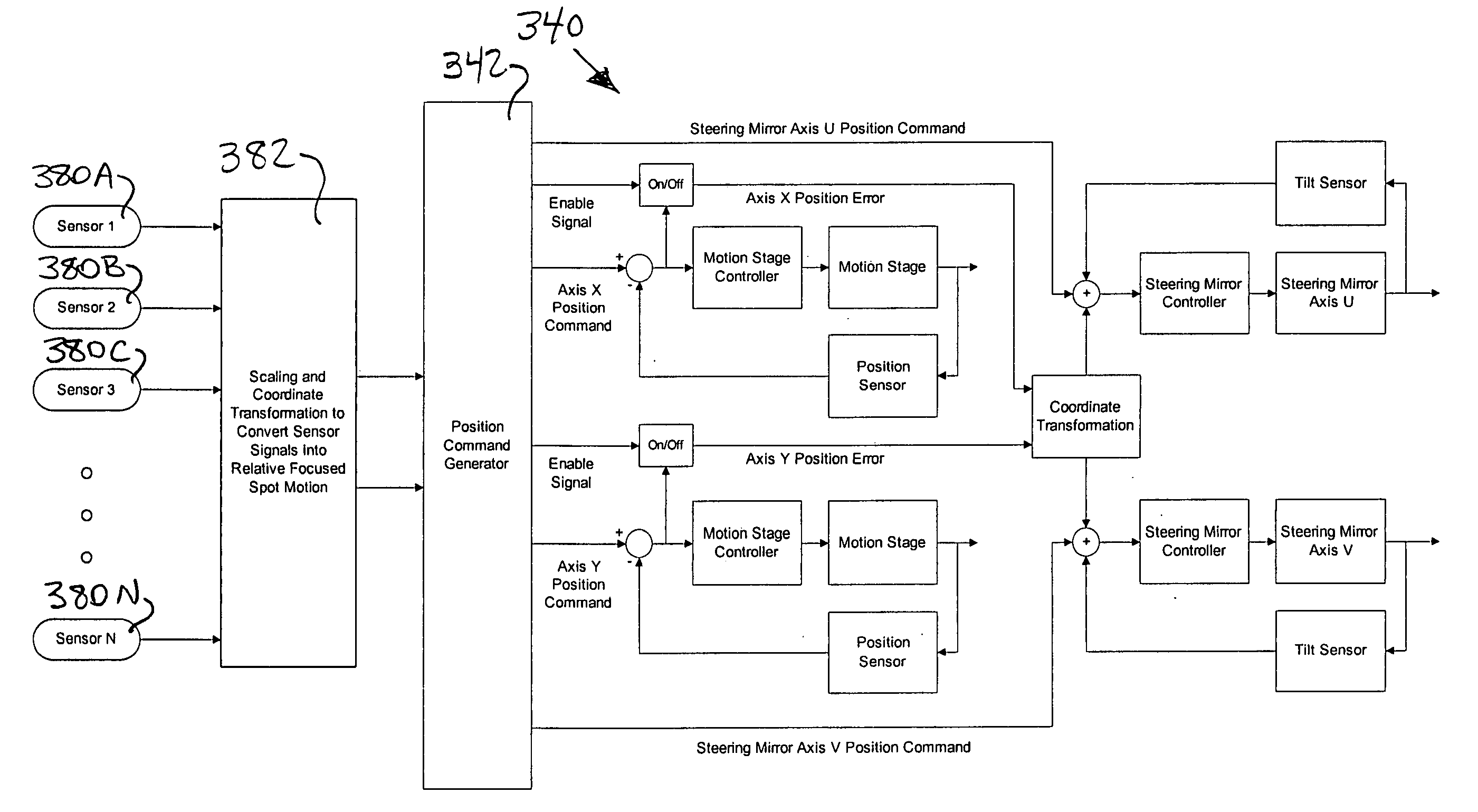
A laser-based workpiece processing system includes sensors connected to a sensor controller that converts sensor signals into focused spot motion commands for actuating a beam steering device, such as a two-axis steering mirror. The sensors may include a beam position sensor for correcting errors detected in the optical path, such as thermally-induced beam wandering in response to laser or acousto-optic modulator pointing stability, or optical mount dynamics.

Description

RELATED APPLICATIONS [0001] This is a continuation-in-part of U.S. patent application Ser. No. 10 / 077,691, filed Feb. 15, 2002, which claims benefit of U.S. Provisional Patent Application No. 60 / 269,646, filed Feb. 16,2001.TECHNICAL FIELD [0002] This invention relates to laser processing of integrated circuit (“IC”) links and, in particular, to a laser system and method employing a laser beam and substrate positioning system that incorporates a steering mirror to compensate for stage positioning errors and enhance link severing throughput. BACKGROUND OF THE INVENTION [0003] Yields in IC device fabrication processes often incur defects resulting from alignment variations of subsurface layers or patterns or particulate contaminants. FIGS. 1, 2A, and 2B show repetitive electronic circuits 10 of an IC device or workpiece 12 that are typically fabricated in rows or columns to include multiple iterations of redundant circuit elements 14, such as spare rows 16 and columns 18 of memory cell...

Claims


Application Information

Patent Timeline
IPC IPC(8): B23K26/02B23K26/08G02B26/08G02B26/10H01L23/525
CPCB23K26/041B23K26/0807Y10S359/90G02B26/101H01L23/5258G02B26/0816H01L2924/0002B23K26/082B23K26/042H01L2924/00
Inventor BRULAND, KELLYVANDERGIESSEN, CLINTGRANT, KEITHSWARINGEN, STEPHEN
Owner ELECTRO SCI IND INC
Learn More