
Non-contact rf id system communication method, non-contact rf id system, transmitter, and receiver

a non-contact, radio frequency identification technology, applied in the direction of burglar alarm mechanical actuation, burglar alarm by hand-portable objects removal, etc., can solve the problems of increasing consumption current, reading errors, and complicated reference circuits, and achieve the effect of easy generation of clock signals

Inactive Publication Date: 2005-11-17
NIPPON TELEGRAPH & TELEPHONE CORP
View PDF4 Cites 12 Cited by
  • Summary
  • Abstract
  • Description
  • Claims
  • Application Information

AI Technical Summary

Benefits of technology

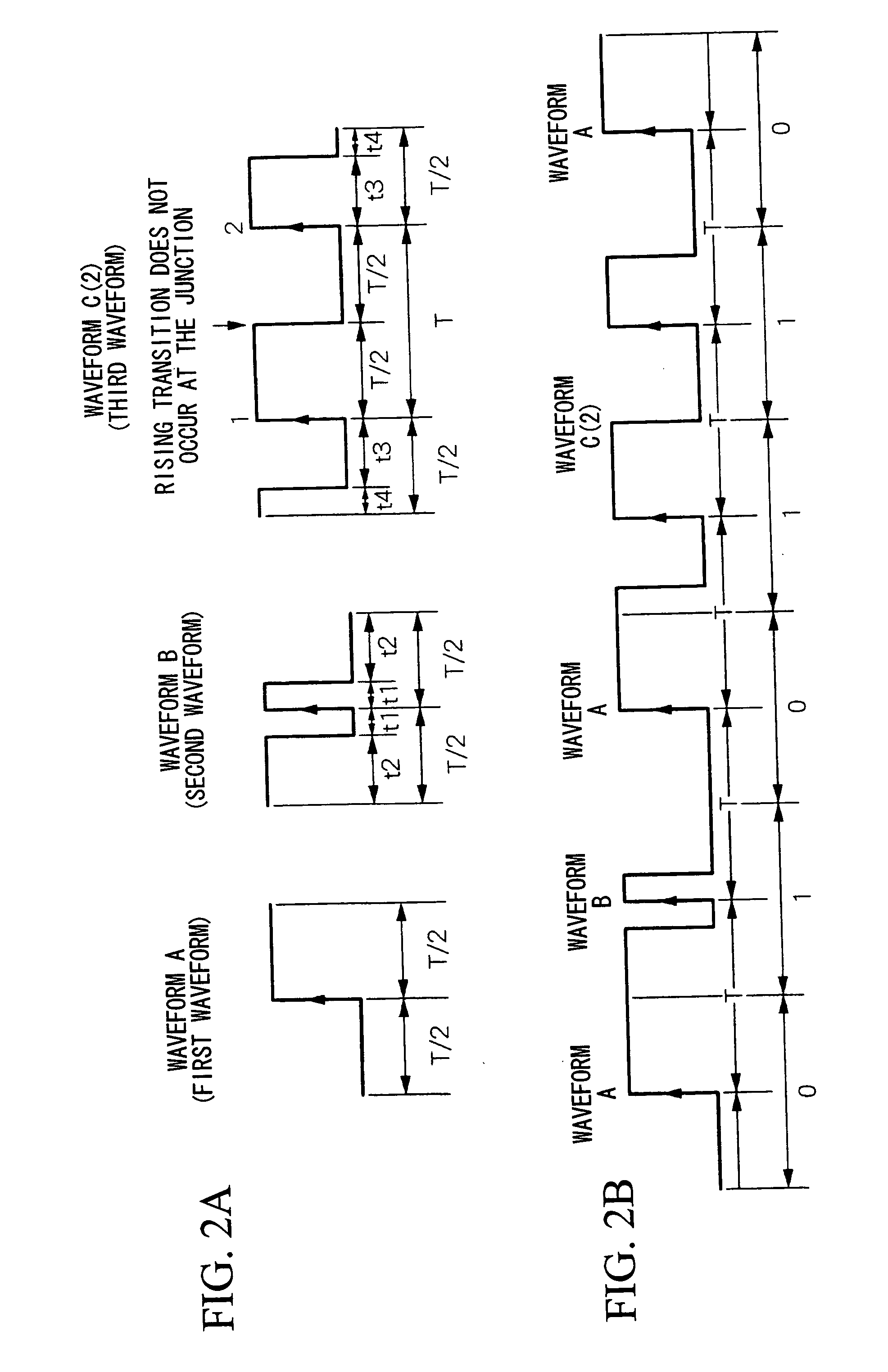
[0034] According to the present invention, the first waveform and the second waveform are formed by the basic waveform that has one of the rising or falling state transitions at the approximate center part of the waveform, and the third waveform is formed by a plurality of basic waveforms having one state transition at the approximate center part of the waveform and the one state transition occurs only at the approximate middle of the plurality of basic waveforms. In the case in which communication is carried out by using the first waveform and the second waveform, if one state transition is generated outside the approximate center part of the plurality of basic waveforms, for example, if the second waveform continues in succession, then transmission is carried out by assigning on the transmission side the third waveform that does not have a rising (or falling) state transition at the junction between the waveforms in place of the second waveform, and on the receiving side, in the case in which the third waveform is received, resolution is carried out by recognizing the reception of successive second waveforms and demodulating them, and thereby it is possible to assign individually the first waveform and second waveform a code “0” and “1”, and thereby it becomes possible to associate a rising (or falling) timing with one unit of data. Thus, by using a circuit that detects the rising (or falling) transition, it is possible to generate easily a clock signal that is in synchronism with the data.

Problems solved by technology

Here, in the case in which the time intervals between the high level and the low level are not equal, that is, in the case in which the duty ratio is not 50%, a DC offset is generated by the data, and this is a significant cause of reading errors when the received signal level fluctuates.
Therefore, a complicated reference circuit becomes necessary, and the consumed current increases.
In cases where the communication is temporarily stopped due to the influence of the state of the radio waves, there are the problems that the convergence of the clock takes time and a long locking time is required.
If each of the independent waveforms A and B is respectively assigned “0” and “1”, then as shown in FIG. 14, when the waveforms B continue in succession, a rising state transition occurs at the junction between the waveforms, and thus associating the rising timing with one unit of data becomes difficult.
However, when assigning the codes “0” and “1” to each of the waveforms A and B independently, as shown in FIG. 14, when the waveforms B continue in succession, a rising state transition occurs at the junction between the two waveforms B, and thus there are problems in that associating the rising timing with one unit of data is difficult, and the transmission efficiency due to the encoding declines.

Method used


Image

  • Non-contact rf id system communication method, non-contact rf id system, transmitter, and receiver
  • Non-contact rf id system communication method, non-contact rf id system, transmitter, and receiver
  • Non-contact rf id system communication method, non-contact rf id system, transmitter, and receiver

Examples


Embodiment Construction

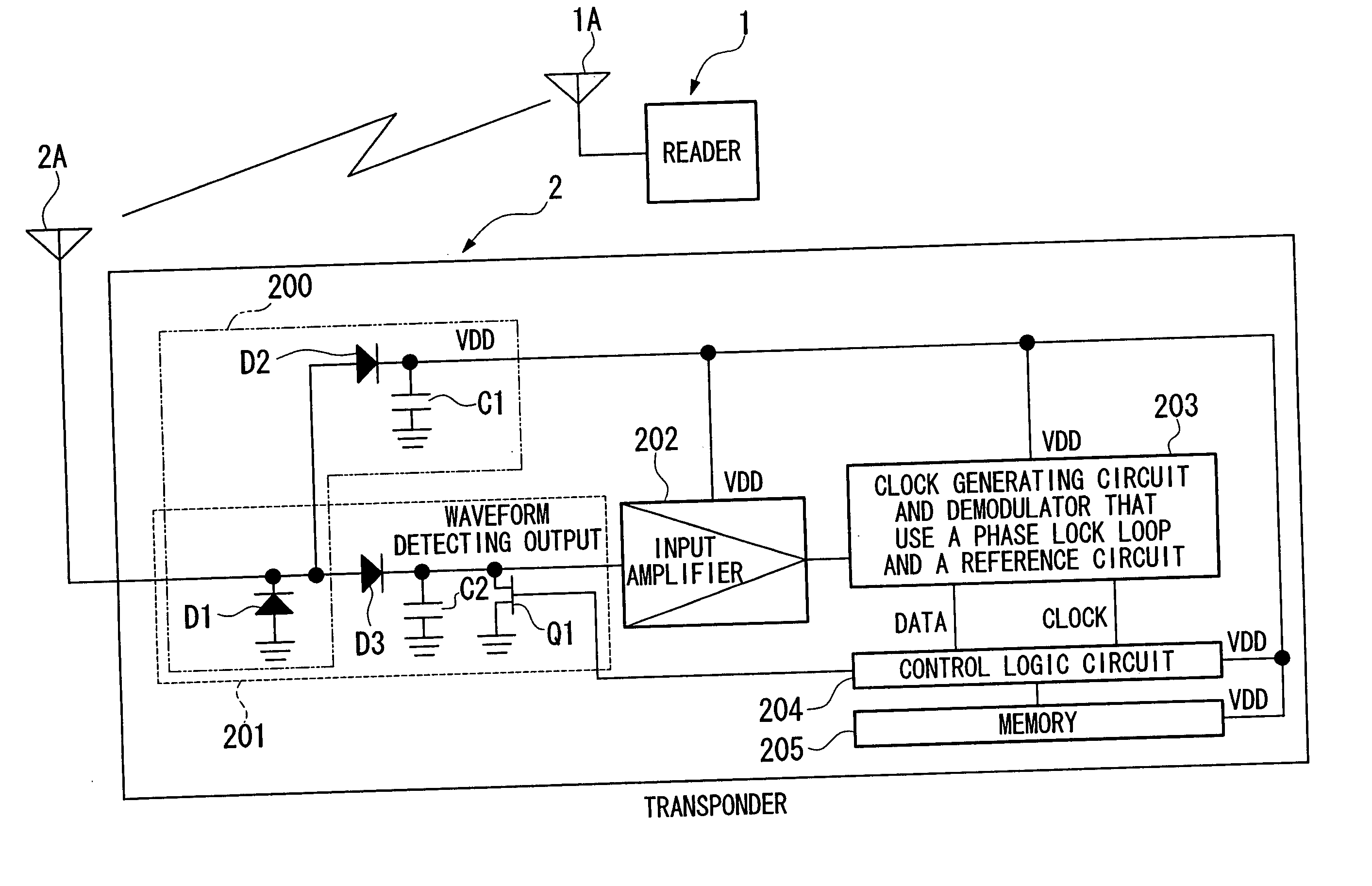
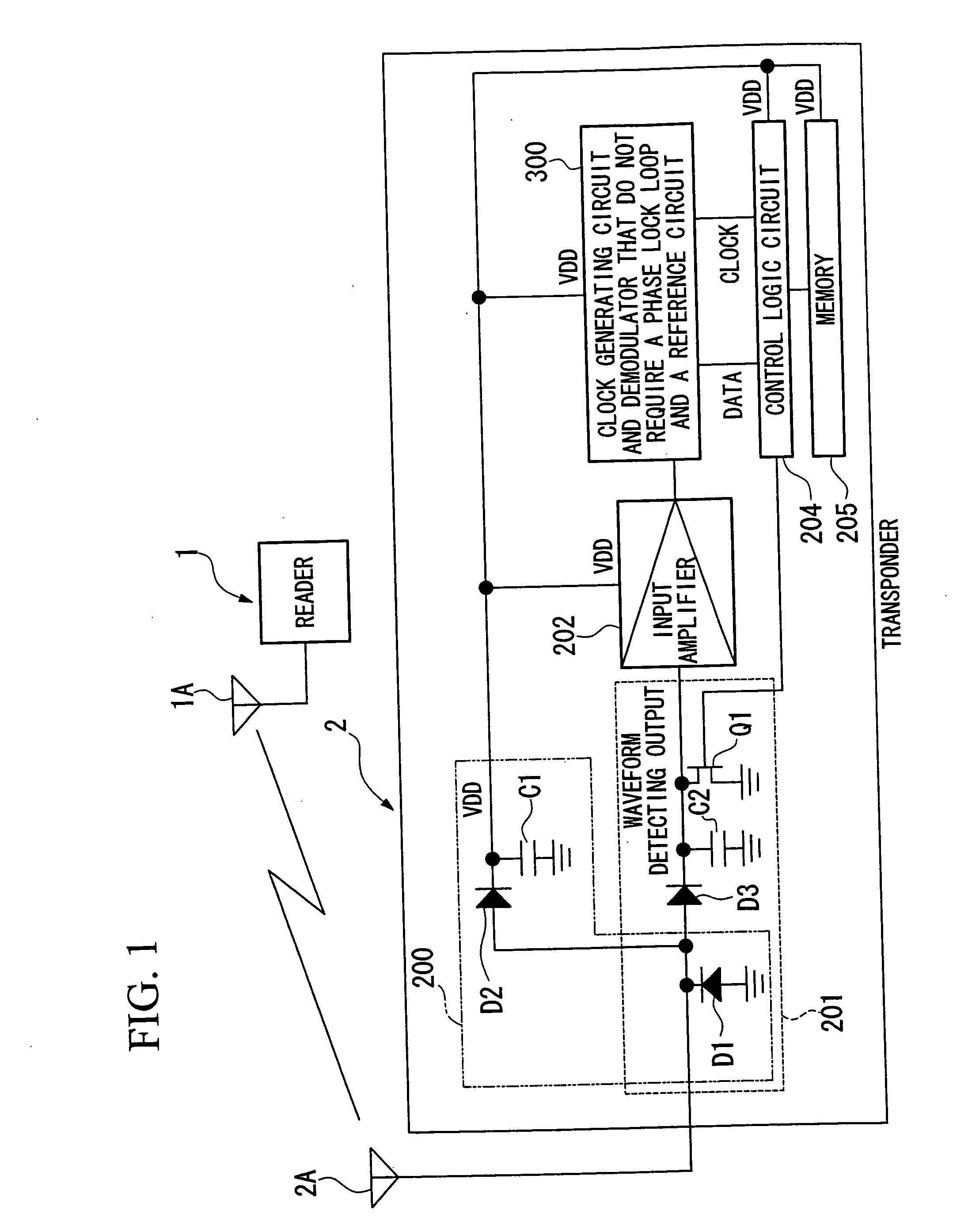
[0051] Below, embodiments of the present invention will be explained in detail with reference to the drawings. The configuration of the noncontact RF ID system of the present embodiment is shown in FIG. 1. As shown in the drawing, the noncontact RF ID system of the present embodiment provides a reader 1 that reads data and a transponder 2 that receives a signal that includes data and a clock signal transmitted from the reader 1. The transponder 2 provides an antenna 2A, a DC power detecting circuit 200, a signal detecting circuit 201, an input amplifier 202, a clock generating circuit and demodulator 300 that do not require a phase locked loop and a reference circuit, a control logic circuit 204, and a memory 205.

[0052] The DC power detecting circuit 200 provides a diode D1, a power source diode D2, and a power accumulating capacitor C1. The signal detecting circuit 201 provides a diode D1, a waveform detecting diode D3, a load capacitor C2, and an FET switch Q1.

[0053] According t...


PUM


Abstract

A communication method for a noncontact RF ID system that uses a first waveform, a second waveform, and a third waveform, wherein the first waveform and the second waveform are formed by a basic waveform having one of a rising or falling state transition at the approximate center of the waveform, the third waveform is formed by a plurality of basic waveforms that have one state transition at the approximate center part of the waveform, and the third waveform generates one state transition only at the approximate center of the plurality of basic waveforms. In addition, communication is carried out by using the third waveform in place of the first waveform and the second waveform in the case in which communication is carried out using a first waveform and a second waveform and one state transition is generated outside the approximate center part of the basic waveform.

Description

TECHNICAL FIELD [0001] The present invention relates to a noncontact RF ID (Radio Frequency IDentification) system, and in particular relates to a communication method for a noncontact RF ID system, a noncontact RF ID system, a transmitter and a receiver that use a code that can separate the data and clock easily without lowering the data transmission speed. BACKGROUND ART [0002] In recent years, with the aim of strengthening information security, high value services, and automation, demand for replacing bar code systems that are applied to distribution systems and magnetic card systems for cashing, commuter passes, or the like, with automatic ID recognition systems that use an IC card or an IC tag, has been increasing. Among these systems, there are one in which the exchange of data and supply of power occurs without directly contacting the reader, that is, wirelessly, and such systems are referred to as “noncontact RF ID systems”. [0003] Noncontact RF ID systems are divided into a...

Claims


Application Information

Patent Timeline
IPC IPC(8): G06K7/00H04L25/49
CPCH04L25/4904G06K7/0008
Inventor HAYASHI, HITOSHISHIMIZU, MASASHITSUBAKI, TOSHIMITSU
Owner NIPPON TELEGRAPH & TELEPHONE CORP
Learn More