
Compact lost motion system for variable value actuation

a lost motion and variable value technology, applied in the direction of non-mechanical valves, valve drives, machines/engines, etc., can solve the problems of increased risk of valve or engine damage or engine failure, difficulty in adjusting the timing and/or amount of engine valve lift, and the inability to operate the vva system

Inactive Publication Date: 2005-11-17
JACOBS VEHICLE SYST
View PDF24 Cites 48 Cited by
  • Summary
  • Abstract
  • Description
  • Claims
  • Application Information

AI Technical Summary

Benefits of technology

The patent describes an innovative system for providing variable valve actuation for internal combustion engines. The system includes a housing with a master piston and a slave piston, a master piston slidably disposed in the master piston bore, and a slave piston slidably disposed in the slave piston bore. The master piston is selectively connected to an input motion, while the slave piston is selectively hydraulically linked to the master piston and is adapted to actuate one or more engine valves. The system also includes a motion imparting device, a rocker arm, and a trigger valve. The patent also describes a fail-safe attribute to the system that ensures safe operation. The technical effects of the invention include improved engine performance and efficiency through variable valve actuation and fail-safe operation.

Problems solved by technology

The use of fixed profile cams, however, can make it difficult to adjust the timings and / or amounts of engine valve lift in order to optimize them for various engine operating conditions, such as different engine speeds.
However, having a hydraulic circuit with various valves transferring motion from a cam or other motion imparting device to an engine valve may possess an increased risk of valve or engine damage or engine failure in the event a solenoid or trigger valve fails.
In such a failure situation, the VVA system may be disabled such that the engine valves associated with the VVA system do not open or close as desired.
This may result in engine failure.
Further, in a failure situation the VVA system may be disabled with an engine valve in an open position.
Such a position may lead to valve or engine damage due to valve-piston contact.
Further, a hydraulic circuit for transferring motion from a cam or other motion imparting device to an engine valve may cause problems for engine valve actuation during start-up and warm-up.
When the engine is started, the hydraulic circuit between the cam and engine valves may be empty, and therefore the valve may not be actuated.

Method used


Image

  • Compact lost motion system for variable value actuation
  • Compact lost motion system for variable value actuation
  • Compact lost motion system for variable value actuation

Examples


Embodiment Construction

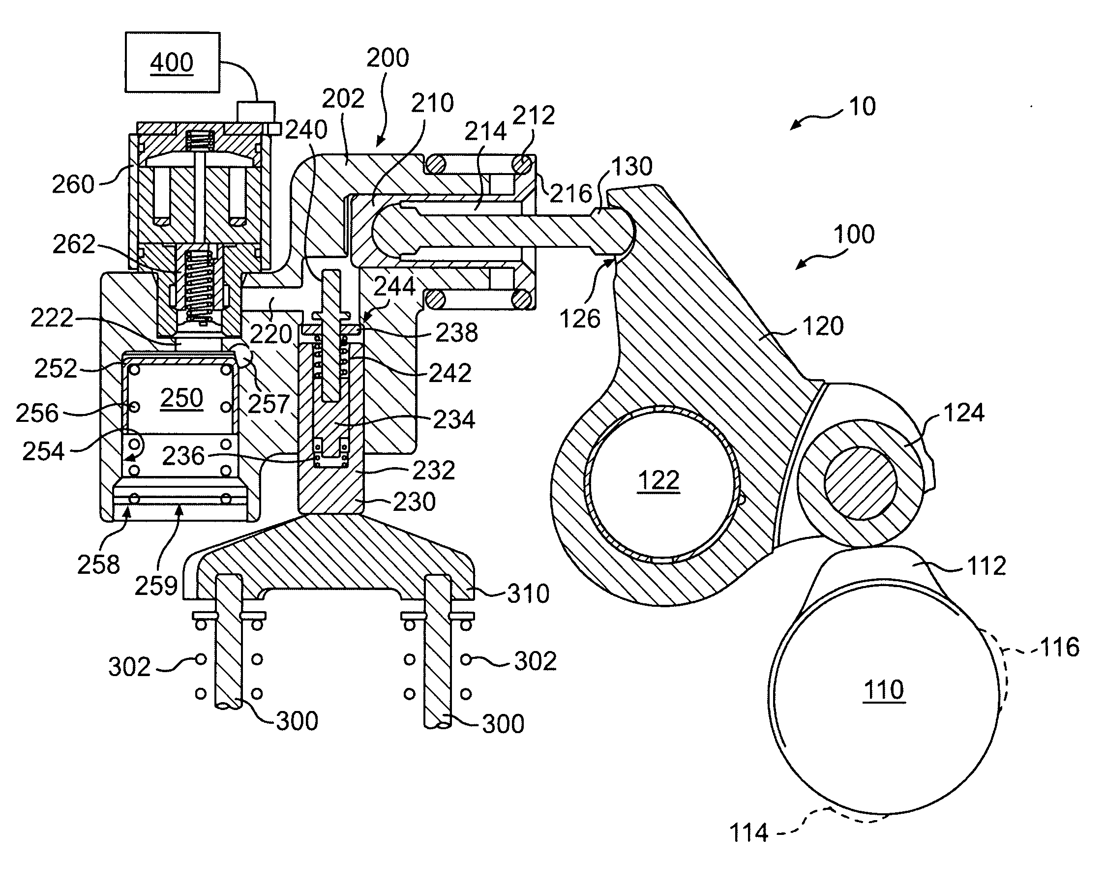
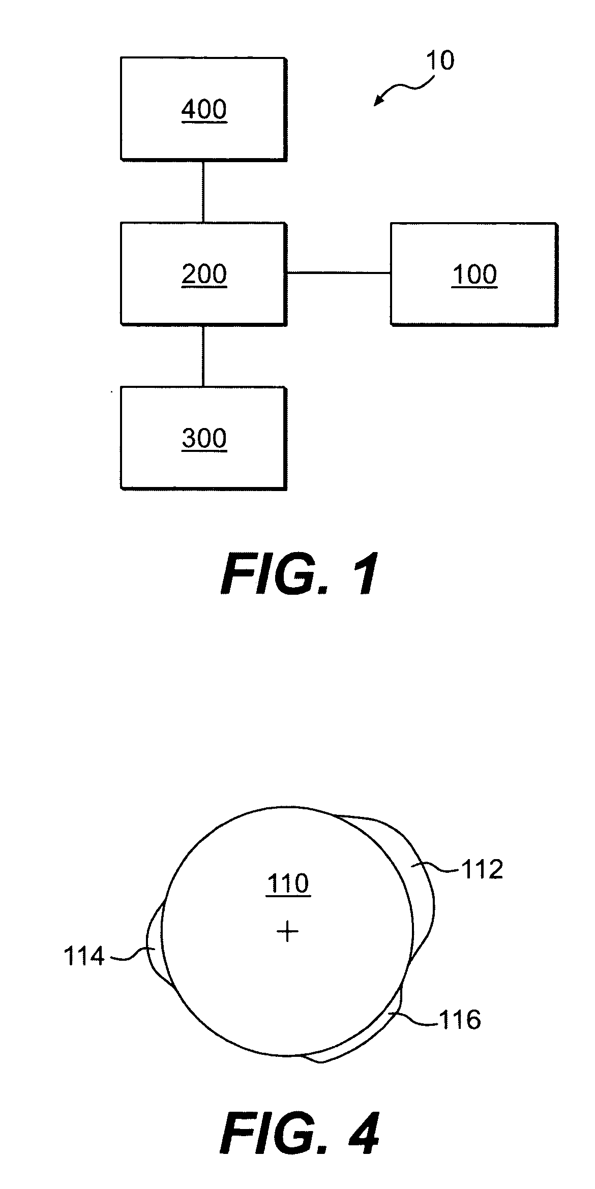
[0054] As embodied herein, the present invention includes both systems and methods of controlling the actuation of engine valves. Reference will now be made in detail to a first embodiment of the present invention, an example of which is illustrated in the accompanying drawings. A first embodiment of the present invention is shown in FIG. 1 as valve actuation system 10. The valve actuation system 10 includes a means for imparting motion 100 (motion means) connected to a lost motion system 200, which in turn is connected to one or more engine valves 300. The motion imparting means 100 provides an input motion to the lost motion system 200. The lost motion system 200 may be selectively switched between modes of: (1) losing the motion input by the motion means 100, and (2) transferring the input motion to the engine valves 300. The motion transferred to the engine valves 300 may be used to produce various engine valve events, such as, but not limited to, main intake, main exhaust, comp...


PUM


Abstract

Lost motion systems and methods for providing engine valves with variable valve actuation for engine valve events are disclosed. The system may include a master piston hydraulically linked to a slave piston, and a dedicated cam operatively connected to the master piston. The slave piston may be disposed substantially perpendicular to the master piston in a common housing. The slave piston is adapted to actuate one or more engine valves. The slave piston may incorporate an optional valve seating assembly into its upper end. A trigger valve may be operatively connected to the master-slave hydraulic circuit to selectively release and add hydraulic fluid to the circuit.

Description

CROSS REFERENCE TO RELATED APPLICATIONS [0001] This application is a continuation in part of, relates to, and claims the priority of U.S. patent application Ser. No. 10 / 408,254 filed Apr. 8, 2003, which relates to and claims priority on U.S. provisional patent application Ser. No. 60 / 370,249 which was filed Apr. 8, 2002.FIELD OF THE INVENTION [0002] The present invention relates generally to a system and method for actuating a valve in an internal combustion engine. In particular, the present invention relates to a system and method that may provide variable actuation of intake, exhaust, and auxiliary valves in an internal combustion engine, and may provide a fail safe method so that the engine may be operated without damage in the event of a component failure. BACKGROUND OF THE INVENTION [0003] Valve actuation in an internal combustion engine is required in order for the engine to produce positive power. During positive power, one or more intake valves may be opened to admit fuel a...

Claims


Application Information

Patent Timeline
Patent Type & Authority Applications(United States)
IPC IPC(8): F01L9/10F01L9/11F01L13/00F01L13/06F01L13/08F02D13/02F02M25/07
CPCF01L1/08Y02T10/121F01L1/181F01L1/24F01L1/26F01L1/267F01L9/02F01L9/021F01L13/0005F01L13/06F01L13/085F01L2001/34446F01L2105/00F01L2810/04F02D13/0207F02D13/0253F02D13/0261F02D13/0273F02D13/0276F02D13/04F02M25/0752F01L1/146F02M26/01F01L2305/00F01L9/11F01L9/10
Inventor VANDERPOEL, RICHARDYANG, ZHOUBRZOSKA, ANDREW J.RUGGIERO, BRIAN L.SMITH, DAVID B.JUDD, JAMESFUCHS, NEIL E.DAILEY, MICHAEL P.ERNEST, STEVEN N.
Owner JACOBS VEHICLE SYST
Learn More