
Coatings for molecule transport and separations

a technology of molecule transport and separation, applied in the direction of coatings, pretreated surfaces, instruments, etc., can solve the problems of adsorption of protein molecules to the capillary walls, unfavorable electroosmotic flow (eof), and difficult separation of proteins by ce, so as to reduce the number of h2o molecules on the surface.

Inactive Publication Date: 2005-11-10
LIU SHAORONG +1
View PDF6 Cites 10 Cited by
  • Summary
  • Abstract
  • Description
  • Claims
  • Application Information

AI Technical Summary

Benefits of technology

[0020] In another embodiment, before the active groups on the solid surface are reacted with the bi-functional reagent, the number of active groups (e.g. —SiOH groups for Si-based materials, —COOH for C-based materials, etc.) is increased and the number of H2O molecules on the surface is reduced.

Problems solved by technology

CE is projected to play a vital role in proteomics research; however, the separation of proteins by CE is not straightforward.
One major problem encountered in CIEF is the adsorption of protein molecules to the capillary walls.
Electroosmotic flow (EOF) is generally unwanted because it moves the ampholyte and the protein sample out of the CIEF capillary during IEF.
The dynamical coatings usually suffer from limited stability and require repeated replenishment for effective operation.
As mass spectrometry (MS) becomes the dominant technique with which protein mixtures are studied, the use of dynamic coatings could be problematic.
The dynamic coating additives often adversely affect the online MS analysis of proteins.
However, the lifetimes of these coatings are usually limited.
Along with its various modifications, this coating has been used for many applications, but the coating quality and stability are inadequate for routine capillary isoelectric focusing of proteins.
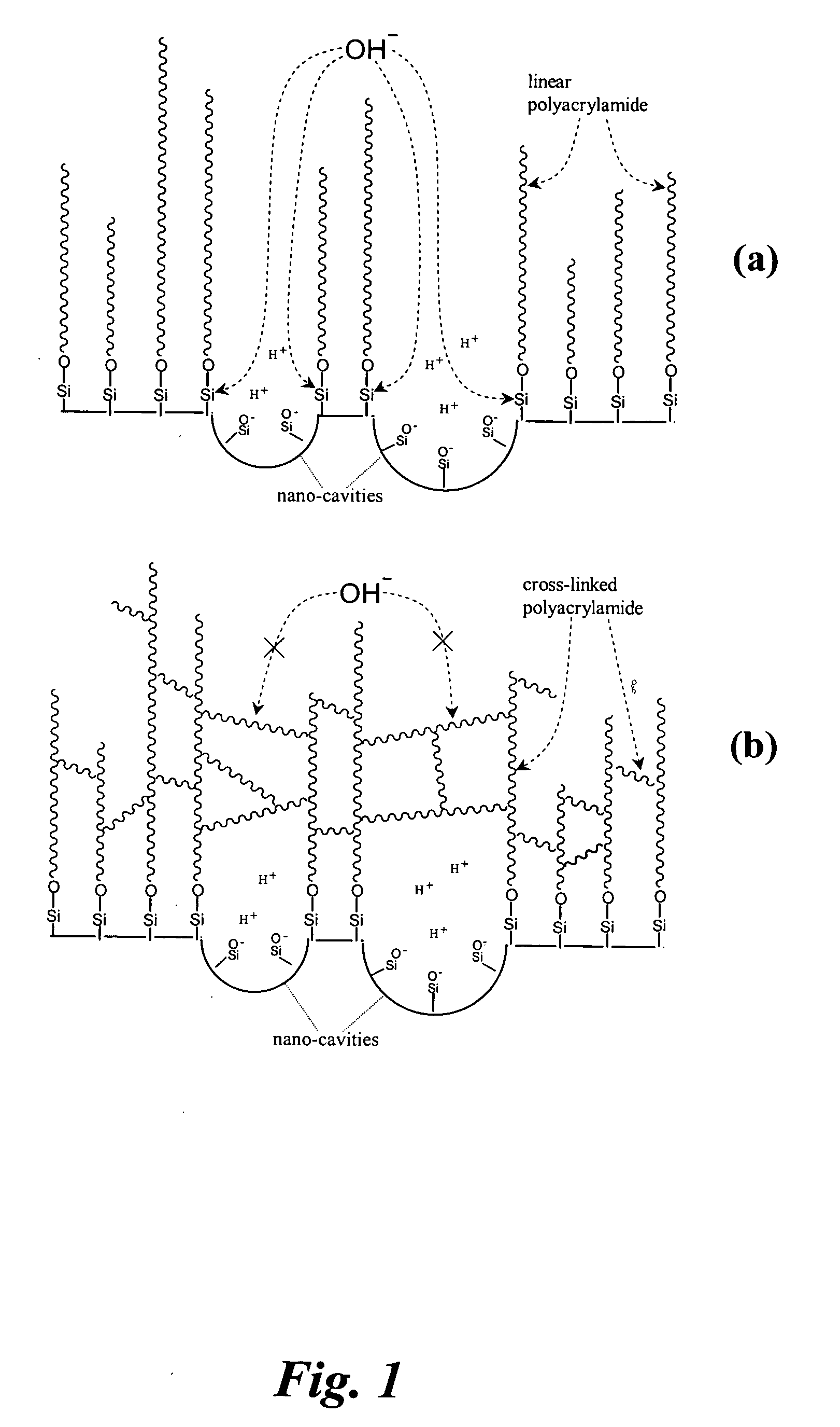
The major problem is that the polyacrylamide molecules cannot cover the capillary wall completely.
Up to date, no modifications have been demonstrated to be adequate for routine high quality CIEF separations.
The resulting products will further hinder the reaction of the bi-functional reagent with the silanol groups in the cavities.
These cavities bring two major problems: (1) polyacrylamide will not be formed on the cavity surfaces, which creates uncoated regions, and (2) OH− and other nucleo-attacking groups can enter the cavity areas to cleave the polyacrylamide molecules anchored around the rims of the cavities, which makes the coating unstable.
In addition to the inconvenience of performing the reactions at elevated temperatures, the dissolved oxygen also interferes with the reaction between the bi-functional groups attached to the capillary surface and a monomer or an oligomer, and therefore, degrades the quality of the coating.
Therefore, the polymer cannot be strongly bonded to the silica surface.
The hydrolysis products will degrade the coating quality.
Because of the surface tension, the solution can not be evenly spread out over the wall surface before and during baking.
This will results in an un-evenly coated surface with many poorly-coated or un-coated spots.

Method used


Image

  • Coatings for molecule transport and separations
  • Coatings for molecule transport and separations
  • Coatings for molecule transport and separations

Examples


example 1

[0055] Preparation of linear polyacrylamide (LPA) coating. Bare capillaries were first washed with 1 M NaOH for 45 min, ultra-pure water and acetonitrile for 15 min each, and then dried with helium. To attach the anchoring functional reagent to the capillary wall, a solution of 0.4% (v / v) of 3-(trimethoxysilyl)propyl methacrylate and 0.2% (v / v) acetic acid in acetonitrile was flushed into the capillaries with a syringe pump at 50 μl / min for 1 h. The capillaries were then rinsed with acetonitrile and dried with helium.

[0056]FIG. 2 presents a device to carry out the polymerization reaction to produce a cross-linked polymer layer on the capillary wall. A 2-mL vial containing 1 mL solution was covered by a septum and clamed together through two ¼-inch-thick acrylic plates. On the top acrylic plate, there were five 1-mm-diameter holes through which the septum was accessible. A small recess on the bottom acrylic plate was used to secure the vial in position. Helium gas was introduced to ...

example 2

[0058] Preparation of cross-linked polyacrylamide (CPA) coatings. The process is the same as described in Example 1, except that the vial in FIG. 2 contained 3-4% of acrylamide (AA) and 0.003-0.03% N,N′-methylene-bis-acrylamide (Bis), and the capillary tip was taken out of the polymerizing solution and quickly flushed with de-ionized water after the polymerizing solution was flushed through the capillary for 4 min, 6 min, 8 min, or 10 min.

example 3

[0059] CIEF Separations. The CIEF separations were performed using a capillary with a total length of 40 cm (an effective length of ca. 36 cm) and an inner diameter of 50 μm, unless otherwise indicated. 10 mM of phosphoric acid and 20 mM of sodium hydroxide were respectively used as anolyte and catholyte. The solution levels in the anolyte and catholyte reservoirs were carefully adjusted to be at the same height. Right before a CIEF separation, a protein sample was mixed with pharmalyte and diluted with water to make the final solution contain 1.8% (w / v) pharmalyte, 7 M urea and a desired amount of protein. After the CIEF capillary was filled with the above protein-pharmalyte mixture, isoelectric focusing was conducted by applying a voltage of 20 kV across the capillary for 20 min. The focused bands were hydrodynamically mobilized to the UV / V is detector after the anolyte reservoir was raised by 2.7 cm. The high voltage was kept on during the mobilization. Between runs, the anolyte ...


PUM


Abstract

A process is disclosed for coating the inner surface of a solid support (e.g. a capillary or a microchip channel) to reduce the analyte adsorption to the surface for separating components in a fluid stream in contact with the surface. The process comprises (a) covalently binding a bi-functional reagent to the support surface, (b) mixing the monomer with a radical initiator under an oxygen-removed environment; and (c) rapidly bringing the above mixture solution to the functionalized surface under an oxygen-free environment.

Description

[0001] This patent application claims the benefit under 35 U.S.C. § 119(e) of U.S. provisional patent application Ser. No. 60 / 568,025, filed on May 4, 2004.BACKGROUND OF THE INVENTION [0002] 1. Field of the Invention [0003] The present invention relates generally to modifications of a solid support surface for conducting molecular transportation, chemical reaction and / or bio-separation, and diagnostics and / or analysis related thereto, and more particularly, to capillary electrophoretic separations of biomolecules. [0004] 2. Description of Related Art [0005] Capillary electrophoresis (CE) has become a powerful analytical technique in recent years due to its high efficiency, short separation time, minimum consumption of sample and reagent, and ease of automation. Its utility has been demonstrated in separations ranging from small molecules, such as inorganic / organic ions, amino acids, and peptides, to biopolymers, including proteins and DNA. CE is projected to play a vital role in pro...

Claims


Application Information

Patent Timeline
IPC IPC(8): B05D1/36B05D3/04G01N33/543
CPCG01N33/54393
Inventor LIU, SHAORONGLU, JUAN
Owner LIU SHAORONG
Learn More