Optical system of a microlithographic projection exposure apparatus

a microlithographic and exposure apparatus technology, applied in the direction of photomechanical apparatus, polarising elements, instruments, etc., can solve the problems of stress-induced birefringence, permanent stress-induced birefringence, and general dissolution of birefringen

Inactive Publication Date: 2005-11-03
CARL ZEISS SMT GMBH
View PDF25 Cites 15 Cited by
  • Summary
  • Abstract
  • Description
  • Claims
  • Application Information

AI Technical Summary

Benefits of technology

[0014] It is therefore an object of the invention to provide an optical system of a microlithographic projection exposure apparatus so that unfavourable effects of intrinsic or induced birefringence on a linear polarization state of transmitted projection light can be reduced in a straightforward way.
[0016] The invention is based on the idea that it is not always necessary to compensate for the birefringent effect of optical elements contained in the optical system. Often it is only important to ensure that the polarization distribution of a projection light beam is perturbed as little as possible. According to the invention, this can be achieved simply by suitably aligning the birefringent material with respect to the polarization distribution. This aligning should be carried out so that—possibly for all light rays passing through the material—their polarization direction is aligned parallel or perpendicularly to a distinguished direction of the birefringence, i.e. the fast or slow axis. Such an alignment ensures that none of the light rays have different polarization components with unequal propagation velocities in the material. This prevents undesirable perturbations of the polarization distribution as they occur with arbitrary alignments.
[0019] It is preferable for the light rays entering the material to be polarized as exactly as possible parallel or perpendicularly to the slow axis of the material. Minor deviations do not, however, substantially degrade the polarization state. With an alignment of the slow birefringent axis parallel to the polarization direction of the respective light ray, the perturbing effect due to the birefringent material is negligible if each light ray entering the material has a polarization direction which deviates from the respective birefringent axis by a value of no more than 15°, preferably no more than 5°.

Problems solved by technology

For example, if a lens mounting exerts mechanical forces on a lens body received therein, these forces lead to stress-induced birefringence, and this birefringence generally vanishes as soon as the lens mounting is removed again.
If the stresses due to external forces remain in the material, then this can lead to permanent stress-induced birefringence.
Such blanks, however, are usually quite expensive.
As it has been found, however, they are intrinsically birefringent for these wavelengths.
If birefringence occurs in a projection objective, unless suitable countermeasures are taken, then this will lead to intolerable contrast losses in the image plane where the photosensitive layer is arranged.
The birefringence has a particularly unfavourable effect when the projection light is intended to arrive at the photosensitive layer with an accurately defined polarization.
However, complete compensation for the birefringence is generally not possible even with an optimum selection of the crystal orientations.
A disadvantage of a complete compensation is furthermore that large numbers of very expensive CaF2 crystals are often necessary, for example with [100] crystal axes being aligned parallel to the optical axis.

Method used


Image

  • Optical system of a microlithographic projection exposure apparatus
  • Optical system of a microlithographic projection exposure apparatus
  • Optical system of a microlithographic projection exposure apparatus

Examples


Embodiment Construction

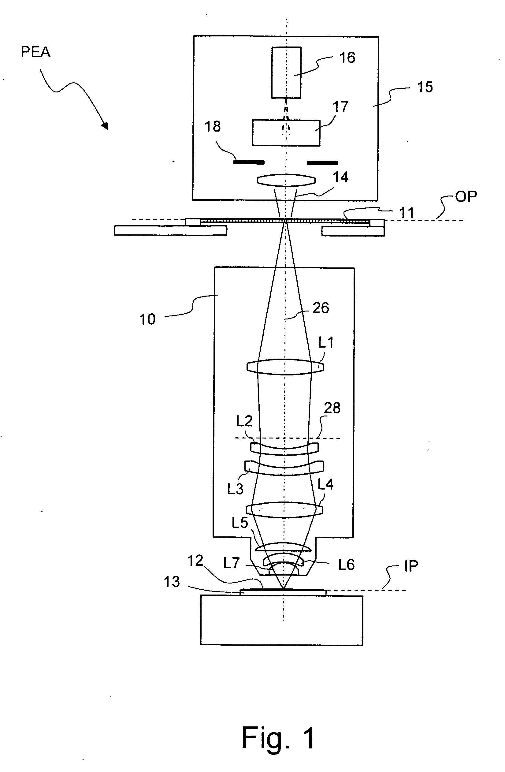
[0038]FIG. 1 shows a meridional section through a microlithographic projection exposure apparatus, denoted in its entirety by PEA, in a highly schematic representation. The projection exposure apparatus PEA comprises an illumination system 15 for producing a projection light beam 14. In the exemplary embodiment shown, the wavelength of the projection light is λ=193 nm. The illumination system 15 contains a light source 16, illumination optics indicated by 17 and a diaphragm 18. The illumination optics 17 makes it possible to set different illumination angle distributions. To this end the illumination system may contain interchangeable diffractive optical elements or microlens arrays, for example. The illumination optics 17 may furthermore contain axicon elements which are arranged so that they can be moved along an optical axis 26. Since such illumination optics are known in the prior art, see for example U.S. Pat. No. 6,285,443 A, whose full disclosure is incorporated herein by ref...


PUM


Abstract

An optical system, for example an illumination system or a projection objective (10), of a microlithographic projection exposure apparatus contains an optical element (L2, L3) which consists of a birefringent material. A projection light beam (14) formed by linearly polarized light rays passes through the optical element (L2, L3). In order to avoid perturbations of the polarization distribution of the light beam, the birefringent material is aligned such that each light ray entering the material is polarized substantially parallel or substantially perpendicularly to a slow birefringent axis for the respective light ray.

Description

BACKGROUND OF THE INVENTION [0001] 1. Field of the Invention [0002] The invention relates to an optical system of a microlithographic projection exposure apparatus, for example an illumination system or a projection objective, in which a projection light beam formed by linearly polarized light rays passes through an optical element which consists of a birefringent material. The invention also relates to a method for reducing perturbations which such a birefringent optical element causes in a given polarization distribution of the projection light beam. [0003] 2. Description of Related Art [0004] The term optical birefringence refers to materials with an anisotropic refractive index. This means that for a light ray passing through the material, the refractive index depends on its polarization and its orientation with respect to the material. The term birefringence in the stricter sense refers to the maximum possible refractive index difference Δn of a birefringent material. Owing to ...

Claims


Application Information

Patent Timeline
IPC IPC(8): G02B13/24G02B5/30G02B13/14G02F1/1335G03F7/20H01L21/027
CPCG02B5/3083G03F7/70966G03F7/70566G02B13/143G03F7/20
Inventor MAUL, MANFREDTOTZECK, MICHAELDITTMAN, OLAFFIOLKA, DAMIAN
Owner CARL ZEISS SMT GMBH
Why Eureka
Try Eureka