Processing apparatus
a technology of processing apparatus and processing chamber, which is applied in the direction of electrical apparatus, hot plate heating arrangement, electric discharge tube, etc., can solve the problems of difficult to attach the lamp to the processing chamber for mechanical reasons, difficult to control the temperature independently of the plasma, and the inability to make space for the lamp within the processing chamber, etc., to achieve the effect of not making the structure inside the table complicated
- Summary
- Abstract
- Description
- Claims
- Application Information
AI Technical Summary
Benefits of technology
Problems solved by technology
Method used
Image


Examples
first embodiment
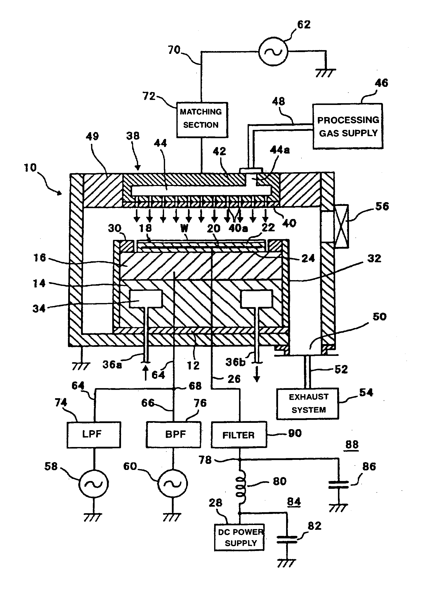
[0026]FIG. 1 shows the structure of a plasma etching apparatus according to the present invention. The plasma etching apparatus of FIG. 1 is a parallel-plate type plasma etching apparatus and includes, for example, a cylindrical chamber (processing chamber) 10 formed of aluminum which has had surfaces alumite treatment (anodization). The chamber 10 is grounded for safety.
[0027] On the bottom of the chamber 10, a columnar support 14 is arranged on an insulation plate 12 formed of ceramic or the like. The support 14 is formed of aluminum, for example. A disc-like susceptor 16 that is formed of aluminum, for example, is provided on the support 14. The susceptor 16 serves as both a table and a lower electrode. A substrate to be processed, for example, the semiconductor wafer W, is placed on the susceptor 16.
[0028] An electrostatic chuck 18 for holding the semiconductor wafer W with a Coulomb force or a Johnson-Rahbeck force is provided on the upper surface of the susceptor 16. The elec...
second embodiment
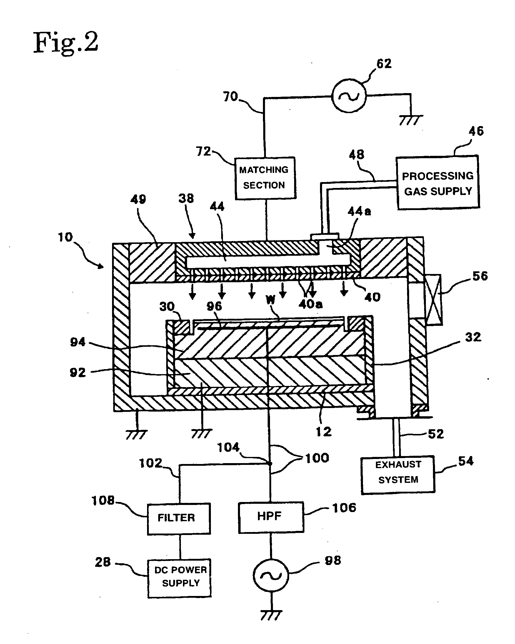
[0049] In the second embodiment, a disc-like susceptor lower electrode 92 formed of aluminum, for example, is arranged at the bottom of the chamber 10 via the insulation plate 12. A susceptor 94 formed of a dielectric material such as ceramic, for example, is provided on the susceptor lower electrode 92. A susceptor upper electrode 96, in the form of a plate or sheet, is provided inside the susceptor 94 so as to be close to the upper surface (substrate-placed surface) of the susceptor 94. The material for the susceptor upper electrode 96 is preferably high-melting point metal such as tungsten, molybdenum, or nickel.
[0050] A radio-frequency power supply 98 causes the susceptor 94, formed of a dielectric material, to generate heat by radio-frequency heating. This allows control of the temperature of the semiconductor wafer W on the susceptor 94 in the heating method. One output terminal of the radio-frequency power supply 98 is electrically connected via a feed line 100 to the suscept...
third embodiment
[0053] In the third embodiment, a coil 110 is provided under the susceptor 94, concentrically with the susceptor 94 or the susceptor electrode 96. A radio-frequency power supply 112 causes the electrode 96 inside the susceptor 94 to generate heat by radio-frequency heating in order to control the temperature of the semiconductor wafer W on the susceptor 94 in the heating method. The radio-frequency power supply 112 is electrically connected at its output terminal to the coil 110 via a feed line 114 and preferably outputs radio-frequency radiation of a frequency in a range from 1 kHz to 10 MHz, for example, radiation of 2 kHz. When the radio-frequency current from the radio-frequency power supply 112 flows through the coil 110, a radio-frequency electromagnetic field J formed by the coil 110 penetrates the susceptor electrode 96, causing the generation of an eddy current in the susceptor electrode 96. The thus generated eddy current causes the susceptor electrode 96 to generate heat,...
PUM
| Property | Measurement | Unit |
|---|---|---|
| Frequency | aaaaa | aaaaa |
| Temperature | aaaaa | aaaaa |
| Power | aaaaa | aaaaa |
Abstract
Description
Claims
Application Information
 - R&D
- Intellectual Property
- Life Sciences
- Materials
- Tech Scout
- Unparalleled Data Quality
- Higher Quality Content
- 60% Fewer Hallucinations
Browse by: Latest US Patents, China's latest patents, Technical Efficacy Thesaurus, Application Domain, Technology Topic, Popular Technical Reports.
© 2025 PatSnap. All rights reserved.Legal|Privacy policy|Modern Slavery Act Transparency Statement|Sitemap|About US| Contact US: help@patsnap.com