
Hollow fiber membrane contact apparatus and process

Inactive Publication Date: 2005-10-20
ENTEGRIS INC
View PDF14 Cites 59 Cited by
  • Summary
  • Abstract
  • Description
  • Claims
  • Application Information

AI Technical Summary

Benefits of technology

[0030] In another aspect of this invention, the shell volume containing the hollow fibers is free of apparatus which promotes turbulent liquid flow within the shell.

Problems solved by technology

Primary among these is the fact that the individual gas and liquid flows cannot be varied independently over wide ranges.
Tray columns are prone to such problems as weeping at low gas flows and flooding at high liquid flows.
Packed towers can flood at high flow rates.
The use of low liquid flow rates in a packed tower can lead to channeling and reduced effective surface area Excessive frothing or foam formation can lead to process inefficiency.
Wetted wall contactors have inherently low mass transfer coefficients, and can flood at high gas flow rates.
As the conditions of the application to which the membrane is being used become more severe, the materials that can be used becomes limited.
For example, the organic solvent-based solutions used for wafer coating in the microelectronics industry will dissolve or swell and weaken most common polymeric membranes.
Being chemically inert, the Poly(PTFE-CO-PFVAE) and FEP polymers are difficult to form into membranes using typical solution casting methods as they are difficult to dissolve in the normal solvents.
Since these chemicals are toxic and dangerous, transport, storage and proper disposal of these chemicals pose serious health and safety hazards to the workers in this industry.
While HF water can easily be produced, a good source for ozonated water has been a challenge.
However, to replace aggressive etch baths, much higher ozone concentration is needed.
This device is characterized by undesirably limited gas mass transfer through the hollow fibers.
Dissolved oxygen in ultrapure water is another problem in semiconductor device manufacturing.
Potential problems associated with uncontrolled oxide growth are prevention of low temperature epitaxy growth, reduction of precise control of gate-oxide films, and increased contact resistance for VIA holes.
Probably because of the impracticality of such a step, this radial stretching step is missing from the disclosed process.
This is a tedious, labor intensive process.
These developers could not be degassed with typical microporous membranes because the liquid would intrude the pores at the pressures used and permeate, causing solution loss and excess evaporation.
While (TFE) membranes would work in these applications, presumably because of their lower surface tension, they are difficult to process into hollow fibers.

Method used


Image

  • Hollow fiber membrane contact apparatus and process
  • Hollow fiber membrane contact apparatus and process
  • Hollow fiber membrane contact apparatus and process

Examples


example 1

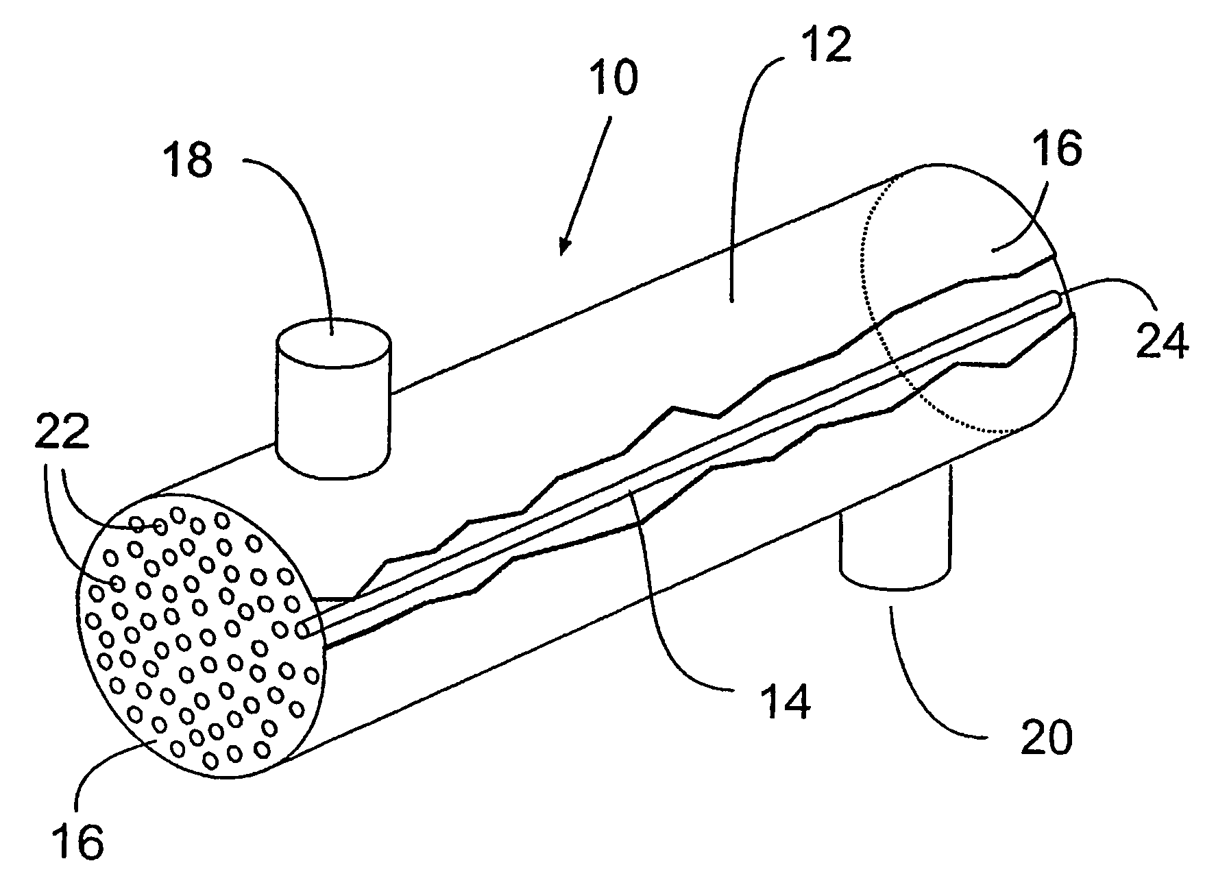
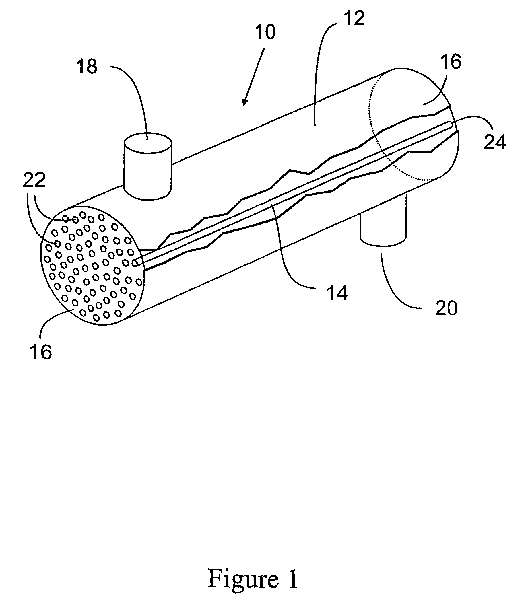
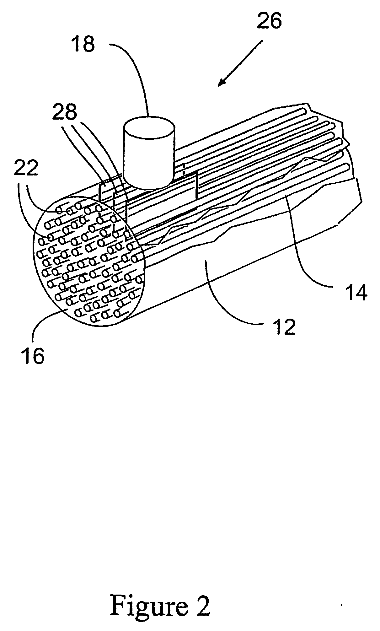
[0082] A contactor with dimensions of 2.25″ ID and 12″ in length was made using porous skinless PFA hollow fibers. The fiber outer diameter (OD) was about 800 microns and the inner diameter (ID) about 500 microns. The number of the fibers was about 2100 and the packing density was around 0.46 m2 of external membrane area / liter of internal cartridge volume. The fiber bundle was potted with an offset of ¼″ gas fitting at both end of the module. Two 1″ fittings for water flow were bonded on the shell at cross-direction near the exit and entrance. The inside of the fitting was reduced to ½″ using an insert to create jetting action of water into the bundle. The water fittings are located perpendicular to the offset of the potting such that a cavity is formed right under the fitting.

[0083] The contactor was tested for ozonation efficiency. Ozone gas at 22 psig., 250 gNm3 and 5 slpm was fed into the gas port of the contactor. Deionized (DI) water was pumped into the contactor using the sh...

example 2

[0084] A contactor with dimensions of 2″ ID and 15″ in length was made using porous skinless PFA hollow fibers. The fiber OD was about 800 micron and the ID about 500 micron. The number of the fibers was about 1700 and the packing density was around 0.42 m2 membrane / liter of internal cartridge volume. The contactor was fitted with ¼″ gas fitting at both end of the module. Two ½″ fitting for water flow were bonded on the shell at cross direction near the exit and entrance.

[0085] The contactor was tested for ozonation efficiency. Ozone gas at 22 psig. 250 g / Nm3 and 5 slpm was fed into the gas port of the contactor. DI water was pumped into the contactor using the shell-side water fitting at a rate of 5 gpm at 25C. The pressure drop was less than 5 psig. The concentration of ozone in the outlet water was measured using an IN-USA ozone sensor. After a couple of minutes, the ozone concentration in the water reached 26 ppm. Under the same operating conditions, the same contactor would pr...

example 3

[0086] A contactor with dimensions of 2.25″ ID and 12″ in length was made using porous skinless PFA hollow fibers. The fiber outer diameter (OD) was about 700 microns and the inner diameter (ID) about 400 microns. The number of the fibers was about 4000 and the packing density was around 0.86 m2 of external membrane area / liter of internal cartridge volume. The fiber bundle was potted with an offset of ¼″ gas fitting at both end of the module. Two 1″ fittings for water flow were bonded on the shell at cross-direction near the exit and entrance. The inside of the fitting was reduced to ½″ using an insert to create jetting action of water into the bundle. The water fittings are located perpendicular to the offset of the potting such that a cavity is formed right under the fitting.

[0087] The contactor was tested for ozonation efficiency. Ozone gas at 22 psig., 250 gNm3 and 5 slpm was fed into the gas port of the contactor. Deionized (DI) water was pumped into the contactor using the sh...


PUM

PropertyMeasurementUnit
Temperatureaaaaaaaaaa
Lengthaaaaaaaaaa
Lengthaaaaaaaaaa

Abstract

The present invention provides a perfluorinated thermoplastic hollow fiber (14) membrane gas-liquid shell side contactor (10) and a process for manufacturing the contactor (10) is described. The present invention also provides a device including a gas-liquid contactor (10) for producing ozonated water.

Description

FIELD OF THE INVENTION [0001] This invention relates to a hollow fiber membrane contactor for phase contact applications. The contactor is made from perfluorinated alkoxy polymeric materials, has a high packing density providing high useful contacting area, and the ability to operate with liquids of low surface tension. BACKGROUND OF THE INVENTION [0002] Liquid-gas contactors are used to transfer one or more soluble substances from one phase to another. Examples of conventional contactors are packed towers, plate columns and wetted wall columns. In these systems, gas absorption of one or more components from a gas stream is accomplished by dispersing the gas as bubbles in packed towers and plate columns in a countercurrent flow to a liquid stream. Absorption efficiency is controlled apart from solubility considerations by the relative rate of the flows and the effective surface area of the gas flow bubbles. In wetted wall contactors the gas stream flows past a downward flow of liqui...

Claims


Application Information

Patent Timeline
IPC IPC(8): B01D19/00B01D53/22B01D61/00B01D63/02B01D67/00B01D69/08B01D71/32B01D71/36B01F23/00C01B13/02C01B13/10C10J1/08
CPCB01D19/0031B01D71/76B01D61/00B01D63/02B01D63/021B01D63/023B01D67/0018B01D67/003B01D69/08B01D71/32B01D71/36B01D2313/14B01F3/04269B01F3/0446B01F5/0453B01F5/0456B01F5/0465B01F2003/0439B01F2003/04404B01F2003/04886C01B13/0255C01B13/10C10J1/08B01D2323/08B01D2325/022B01D2325/20B01D53/22B01F23/23124B01F23/231244B01F23/232B01F23/237613B01F25/3132B01F25/31322B01F25/313311B01F23/00B01F23/20B01D2323/081B01D63/031B01D63/0233
Inventor PAREKH, BIPIN S.PATEL, RAJNIKANT B.CHENG, KWON-SHUN
Owner ENTEGRIS INC
Learn More