Resin particle, conductive particle and anisotropic conductive adhesive containing the same

a technology of anisotropic conductive adhesive and conductive particle, which is applied in the direction of connection contact material, cellulosic plastic layered product, natural mineral layered product, etc., can solve the problem of damaged adhesion body and achieve the effect of high conductive reliability

Inactive Publication Date: 2005-10-13
SONY CORP
View PDF0 Cites 14 Cited by
  • Summary
  • Abstract
  • Description
  • Claims
  • Application Information

AI Technical Summary

Benefits of technology

[0015] In the conductive particle according to the present invention, a conductive layer is formed by, e.g., adhering the conductive material to a surface of the resin particle as described above, and such conductive particles are dispersed at a predetermined proportion in the adhesive material to manufacture the anisotropic conductive adhesive, and when the above anisotropic conductive adhesive is used for carrying out coupling of wiring boards, the electric device enjoying a high conductive reliability can be obtained because the conductive particles sandwiched by the wiring boards are greatly compressed as deformed by a small load and also because the resin particle in the conductive particle is not broken down in a case of compressed and deformed by 60%.

Problems solved by technology

If a load necessary for compression is large even where the maximum compression deformation ratio is high, it may cause an adhered body to receive damages.

Method used


Image

  • Resin particle, conductive particle and anisotropic conductive adhesive containing the same
  • Resin particle, conductive particle and anisotropic conductive adhesive containing the same
  • Resin particle, conductive particle and anisotropic conductive adhesive containing the same

Examples


Embodiment Construction

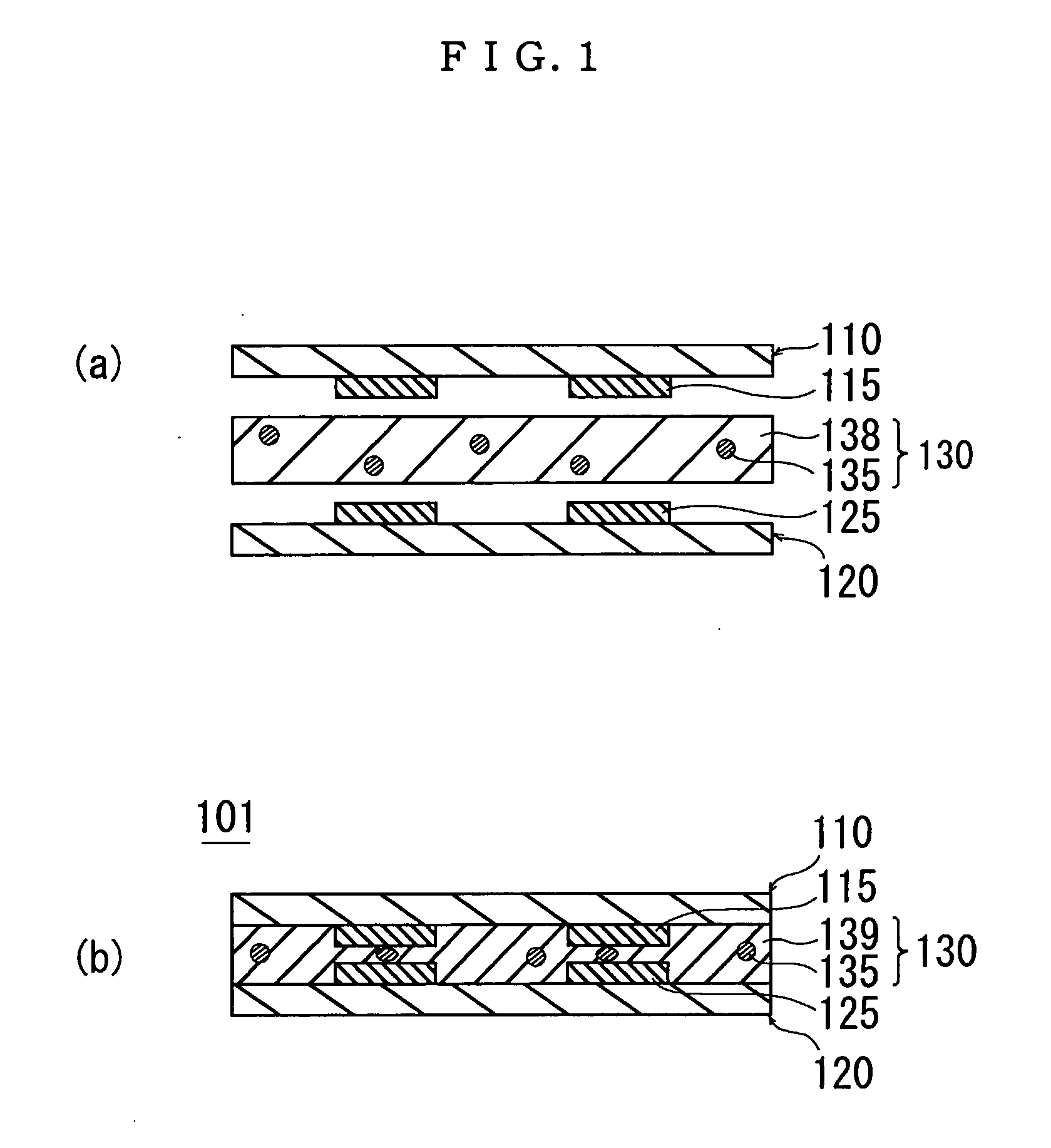
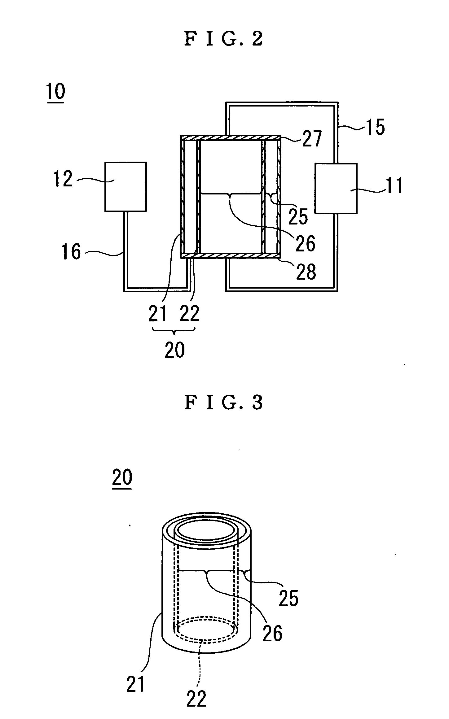
[0024] Hereinafter, a resin particle, a conductive particle, and an anisotropic conductive adhesive under application of the present invention will be described in detail with reference to the figures.

[0025] First, in the resin particle according to the present invention, a main component is an acrylic resin; the maximum compression deformation ratio of the resin particle is 60% or more; and a load necessary for compression deformation is less than or equal to 60 mN. It is especially preferable that the load necessary for the compression deformation is less than or equal to 30 mN.

[0026] It is to be noted that the compression deformation ratio according to the present invention is defined as a value represented by the following formula (1) on the condition that a particle size (initial particle size) of the resin particle before exertion of the load is set to R0 while a particle size thereof at a time exerting the load is set to R1 where the resin particle is, based on a micro pres...


PUM

PropertyMeasurementUnit
diameteraaaaaaaaaa
Compression Ratioaaaaaaaaaa
Particle Sizeaaaaaaaaaa

Abstract

Resin particles comprised of an acrylic resin. Not only is the maximum compression deformation ratio thereof as great as 60% or more but also the load required for 60% compression deformation is as small as 60 mN or less. Wiring boards are therefore coupled in using an anisotropic conductive adhesive obtained by first manufacturing conductive particles having a conductive coating formed on a resin particle surface of the resin particles by adhering a conductive material to the surface of the above resin particles as a core. On dispersing the conductive particles in an adhesive material, the conductive particles sandwiched between metallic wires of the wiring boards are greatly deformed by a small load, so that the electrical devices having a high conduction reliability can be obtained.

Description

TECHNICAL FIELD [0001] This invention relates to a resin particle and a conductive particle containing the resin particle as a core material thereof and further to an anisotropic conductive adhesive containing the conductive particles. BACKGROUND ART [0002] Conventionally, an anisotropic conductive adhesive in which conductive particles are dispersed within an adhesive material has been widely used in coupling or assembling semiconductor devices, wiring boards, or the like. [0003] Situations where two wiring boards are coupled in using the anisotropic conductive adhesive of the conventional art will be explained. FIG. 1(a) is an illustration of a process for coupling a wiring board 110 and a wiring board 120 to each other by means of the anisotropic conductive adhesive with use of the conductive particles, showing as a state prior to pressuring with heating. After rendering a metallic wiring 115 of the wiring board 110 and a metallic wiring 125 of the wiring board 120 face to each o...

Claims


Application Information

Patent Timeline
Patent Type & Authority Applications(United States)
IPC IPC(8): C08F2/00C08J3/12C09C3/10C09J9/02H01R4/04H01R4/58H05K3/32
CPCC08J3/128Y10T428/2995C09C3/10C09J9/02H01R4/04H01R4/58H05K3/323H05K2201/0221H05K2201/0233Y10T428/2993Y10T428/2998Y10T428/2982Y10T428/2991Y10T428/2996C08J2333/06C01P2004/84
Inventor KAMIYA, KAZUNOBUKOJIMA, RYOJI
Owner SONY CORP
Why Eureka
Try Eureka