
Method for measuring and manufacturing an optical element and optical apparatus

a manufacturing method and optical element technology, applied in the direction of instruments, geometric properties/aberration measurement, structural/machine measurement, etc., can solve the problems that the effect of spherical lenses produced by using such conventional methods in practice does not meet the high requirements of the standard, and achieves the effect of high precision and simple manner

Inactive Publication Date: 2005-10-13
CARL ZEISS SMT GMBH
View PDF17 Cites 26 Cited by
  • Summary
  • Abstract
  • Description
  • Claims
  • Application Information

AI Technical Summary

Benefits of technology

[0013] Embodiments of the present invention provide a method of processing an optical surface of an optical element by which an optical surface of the optical element can be measured and manufactured with a high precision in a relatively simple manner.
[0014] Further embodiments of the invention provide an optical apparatus for providing a fine adjustment of optical elements with respect to each other.
[0036] For example, when only one of the threaded bolts is actuated, its corresponding supporting location will move readily. As the supporting location supports the curved optical surface of the lens, the lens will experience a tilting effect. On the contrary, when actuating all three bolts by a same amount the lens will experience a translation which is substantially in the direction of the optical axis of the lens. The threaded portions, and likewise the threaded bolts, might be arranged regularly, such that the central axis of the three threaded portions are within one same plane and intersecting within a central point, defined by equal distances to the threaded portions. But the threaded portions and bolts might also be oriented in a more general manner, which might be of advantage, when actuators requiring a substantial amount of space have to be used to actuate the threaded bolts. Thus it is an advantage when a first diameter of a smallest first mathematical sphere which has the central axes of the three adjustment members (e.g., threaded bolts) as tangents is less than half of a smallest second mathematical sphere on the surface of which the three supporting locations are located.

Problems solved by technology

It has been found that aspherical lenses being produced by using such conventional methods in practice do not meet high requirements concerning their effect in an optical system in which they are to be integrated.
A further problem concerning conventional types of interferometers is to provide a fine adjustment of the optical elements comprising the interferometer to an extent which is substantially less than a movement as performed by conventional actuators.

Method used


Image

  • Method for measuring and manufacturing an optical element and optical apparatus
  • Method for measuring and manufacturing an optical element and optical apparatus
  • Method for measuring and manufacturing an optical element and optical apparatus

Examples


Embodiment Construction

[0054] In the exemplary embodiments described below, components that are alike in function and structure are designated as far as possible by alike reference numerals. Therefore, to understand the features of the individual embodiments and their components, the descriptions of other embodiments and their components and of the summary of the invention should be referred to.

[0055] The embodiments described below utilize interferometric measurement techniques. Suitable interferometric measurment techniques are known in the art, such as, for example, the interferometric measurement techniques are described in U.S. Pat. No. 5,361,312, U.S. Pat. No. 5,982,490, and U.S. 2002 / 0063867 A1. The entire contents of these documents are incorporated herein by reference.

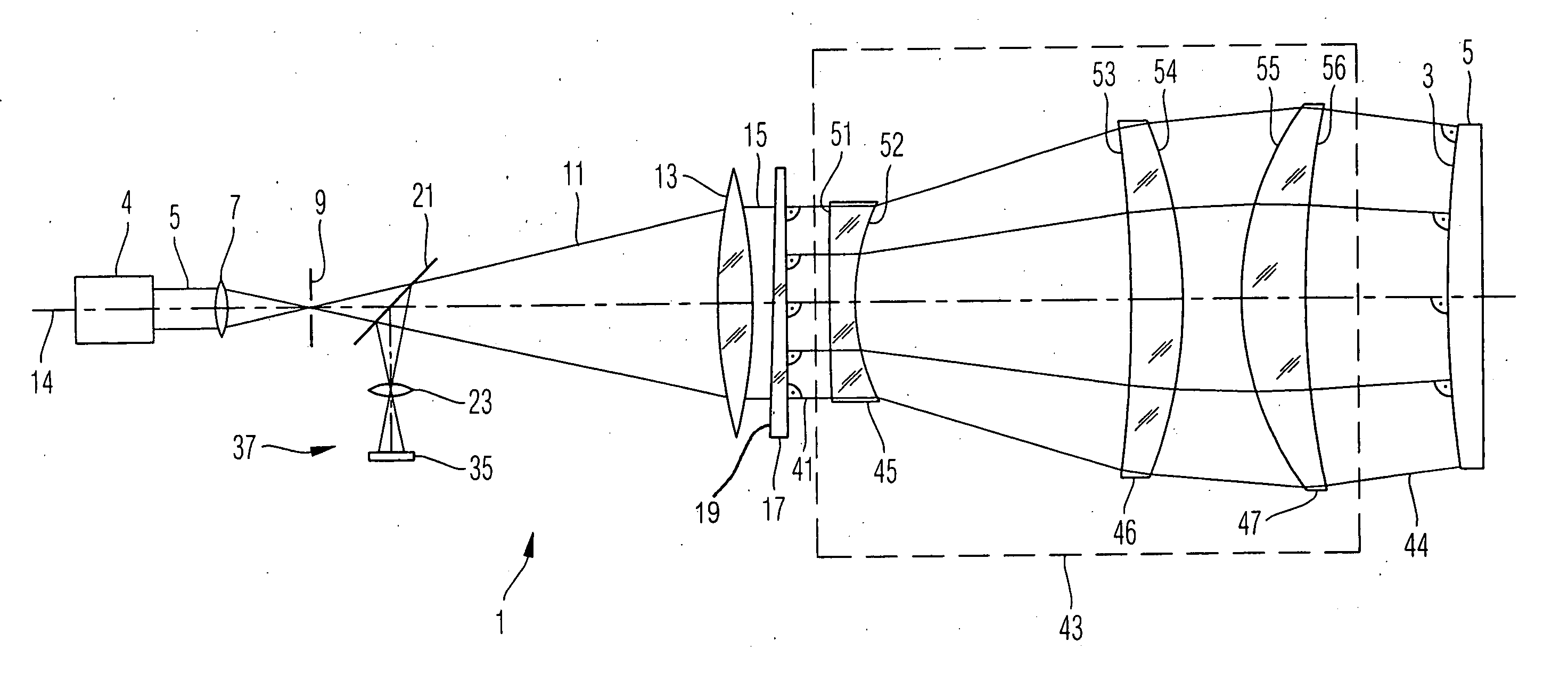
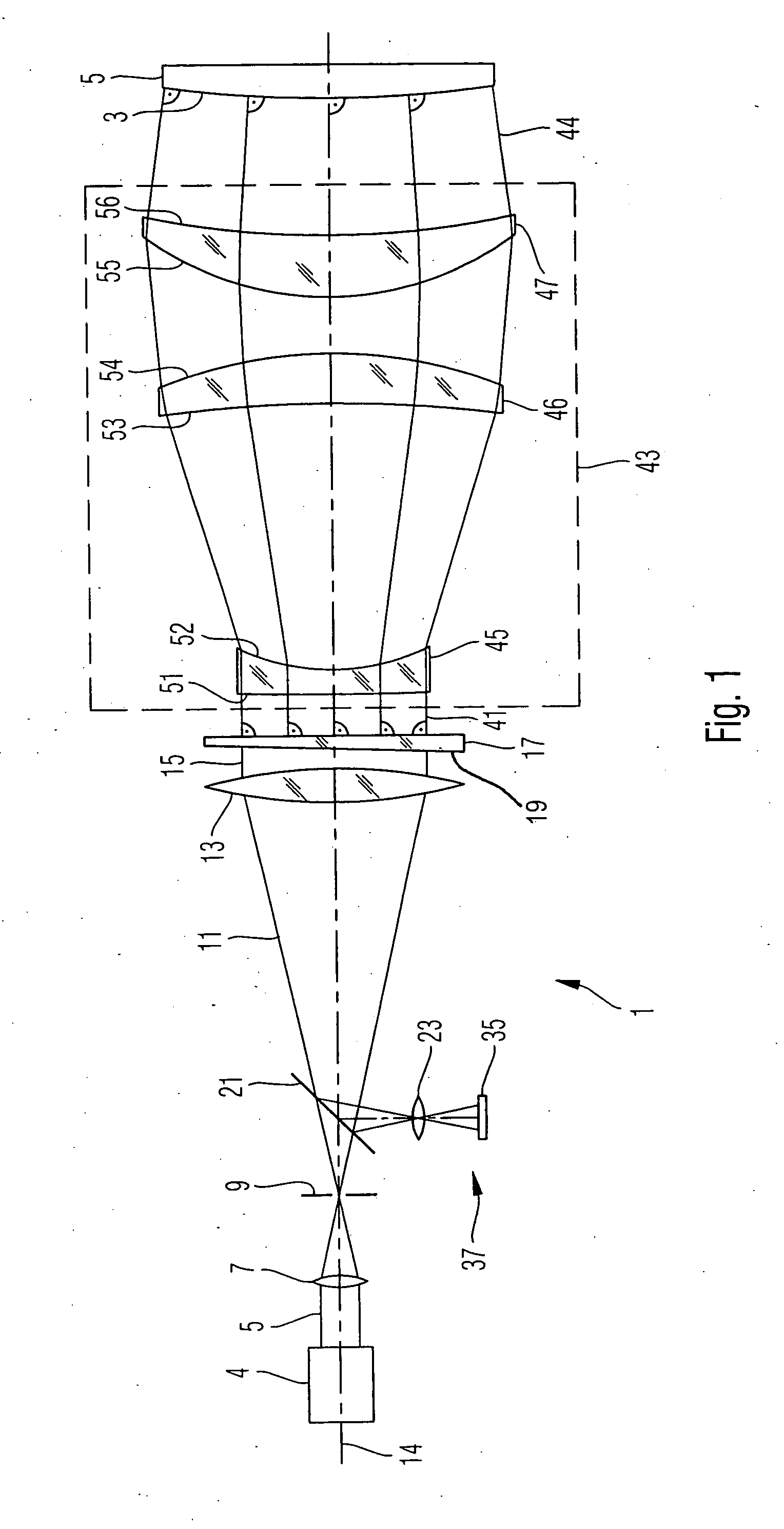
[0056]FIG. 1 shows an interferometer system 1 for measuring an aspherical reflecting surface 3, or aspherical mirror surface 3, of a mirror 5. The interferometer system 1 comprises a light source 4, as for example a helium neon la...


PUM


Abstract

A method of processing an optical element comprises testing the optical surface of the optical element using an interferometer optics for generating a beam of measuring light; wherein the interferometer optics has a plurality of optical elements which are configured and arranged such that the measuring light is substantially orthogonally incident on a reflecting surface, at each location thereof; and wherein the method further comprises: measuring at least one property of the interferometer optics, disposing the optical surface of the optical element at a measuring position relative to the interferometer optics within the beam of measuring light, and performing at least one interferometric measurement; determining deviations of the optical surface of the first optical element from a target shape thereof, based on the interferometric measurement and the at least one measured property of the interferometer optics.

Description

[0001] This application claims priority under 35 U.S.C. 119 to German Patent Application No. 10 2004 016 737.0 filed Apr. 5, 2004, the entire contents of which are incorporated herein by reference. BACKGROUND OF THE INVENTION [0002] 1. Field of the Invention [0003] The present invention relates to method for processing an optical element having an optical surface of a target shape. Particularly, the invention relates to measuring and manufacturing optical elements having surfaces of an aspherical shape. Further, the invention relates to an optical apparatus having at least two lenses and a mounting structure for adjustably supporting at least one of the lenses. [0004] 2. Brief Description of Related Art [0005] An optical element having an optical surface may comprise, for example, an optical component such as an optical lens or an optical mirror used in optical systems, such as telescopes used in astronomy, and systems used for imaging structures, such as structures formed on a mask...

Claims


Application Information

Patent Timeline
IPC IPC(8): G01B9/02G01M11/02G02B13/18G02B27/62
CPCG01M11/0214G01M11/025G02B27/62G02B13/18G01M11/0271
Inventor FREIMANN, ROLFBEDER, SUSANNESEITZ, GUENTHERSCHILLKE, FRANKDOERBAND, BERNDMARTIN, HEINZKRUG, FRANZ
Owner CARL ZEISS SMT GMBH
Learn More