Thermal barrier coating, manufacturing method thereof, turbine part and gas turbine
- Summary
- Abstract
- Description
- Claims
- Application Information
AI Technical Summary
Benefits of technology
Problems solved by technology
Method used
Image
Examples
first embodiment
A. First Embodiment
(Layers of the Thermal Barrier Coating)
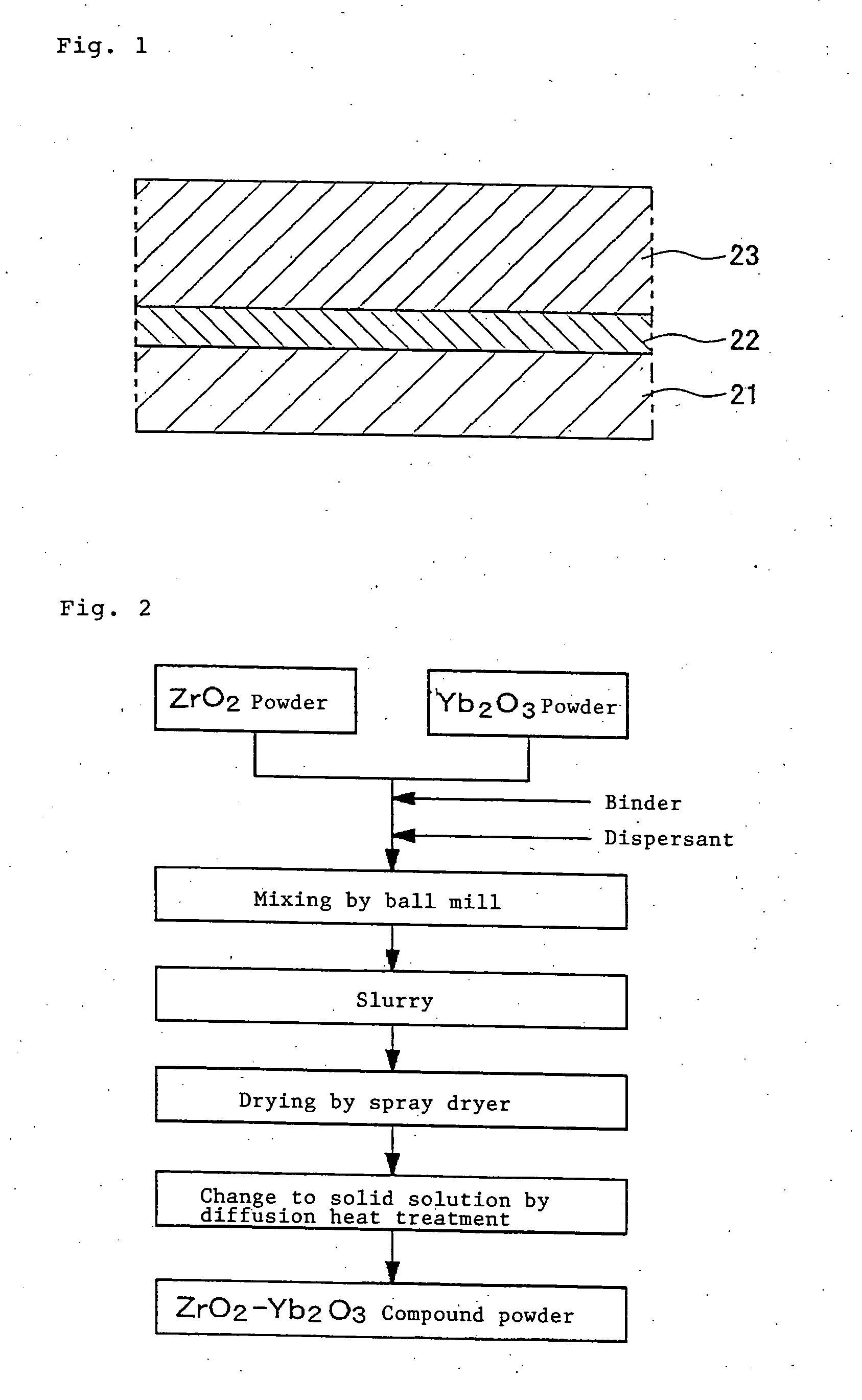
[0045]FIG. 1 is a view schematically showing a cross sectional structure of layers of a first embodiment of a thermal barrier coating according to the present invention. This thermal barrier coating is constructed such that a bond coat layer 22 comprising an MCrAlY alloy, etc. as a metallic bond layer excellent in the corrosion resistance and oxidation resistance is laminated on a base material 21 of a high temperature heat resistant alloy for a moving blade, etc. and, further thereon, a ceramics layer 23 comprising ZrO2 partially stabilized by Yb2O3 (hereinafter referred to as “YbSZ”) as a top coat is laminated. Here, “M” of the MCrAlY alloy constructing the bond coat layer 22 means a metal element, for example, a single metal element of Ni, Co, Fe, etc. or a combination of two or more kinds of these metal elements.
[0046] The bond coat layer 22 has a function to lessen the difference in the thermal expansion coefficient b...
second embodiment
B. Second Embodiment
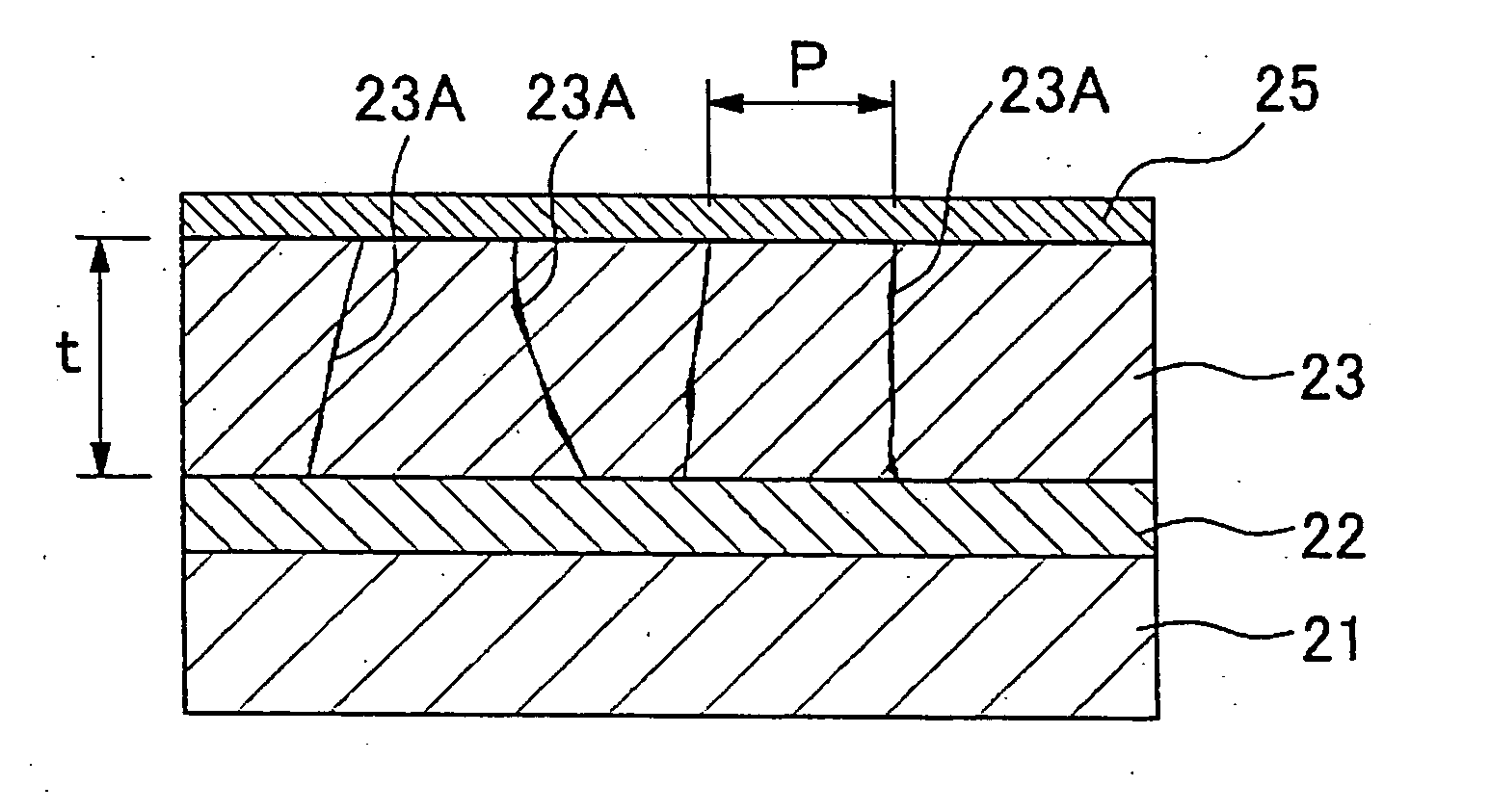
[0059] A second embodiment according to the present invention will be described with reference to FIG. 3. FIG. 3 is a view schematically showing a cross sectional structure of layers of a thermal barrier coating of the second embodiment according to the present invention. The same parts or components in FIG. 3 as those shown in FIG. 1 are designated by the same reference numerals and description thereon will be omitted. The thermal barrier coating of the second embodiment is likewise constructed such that the bond coat layer 22 is formed on the base material 21 of a heat resistant alloy and the ceramics layer 23 is laminated on this bond coat layer 22.
[0060] The difference of the thermal barrier coating of the present, embodiment from the thermal barrier coating shown in FIG. 1 is that the ceramics layer 23 has a plurality of cracks 23A formed therein so as to elongate in the coating thickness direction, as shown in FIG. 3. These cracks 23A are intentionally int...
example 1
[0077] In the present example, in order to verify a change in the thermal cycle life corresponding to the addition quantity of Yb2O3, samples having a YbSZ layer in which a Yb2O3 addition quantity in ZrO2 is variously changed are formed and the thermal cycle life is measured. A base material used for forming the samples is a Ni base heat resistant alloy and the alloy composition is Ni—16Cr—8.5Co—1.7Mo—2.6W—1.7T—0.9Nb—3.4Al—3.4Ti. This base material has its surface applied with a grid blast treatment using Al2O3 grains and, thereon, a bond coat layer made of a CoNiCrAlY alloy having a composition of Co—32Ni—21Cr—8Al—0.5Y as a metal bond layer is formed by a low pressure plasma thermal spraying. A ceramics layer (YbSZ layer) is laminated on this bond coat layer of CoNiCrAlY by an atmospheric pressure plasma thermal spraying so that a thermal barrier coating is formed. A diffusion heat treatment temperature for making the ZrO2—Yb2O3 compound powder used for the thermal spraying of the ...
PUM
| Property | Measurement | Unit |
|---|---|---|
| Percent by mass | aaaaa | aaaaa |
| Percent by mass | aaaaa | aaaaa |
| Percent by mass | aaaaa | aaaaa |
Abstract
Description
Claims
Application Information
 - Generate Ideas
- Intellectual Property
- Life Sciences
- Materials
- Tech Scout
- Unparalleled Data Quality
- Higher Quality Content
- 60% Fewer Hallucinations
Browse by: Latest US Patents, China's latest patents, Technical Efficacy Thesaurus, Application Domain, Technology Topic, Popular Technical Reports.
© 2025 PatSnap. All rights reserved.Legal|Privacy policy|Modern Slavery Act Transparency Statement|Sitemap|About US| Contact US: help@patsnap.com


