
Latching quick-connect connector

Inactive Publication Date: 2005-10-06
DRYER JOSEPH E
View PDF48 Cites 13 Cited by
  • Summary
  • Abstract
  • Description
  • Claims
  • Application Information

AI Technical Summary

Benefits of technology

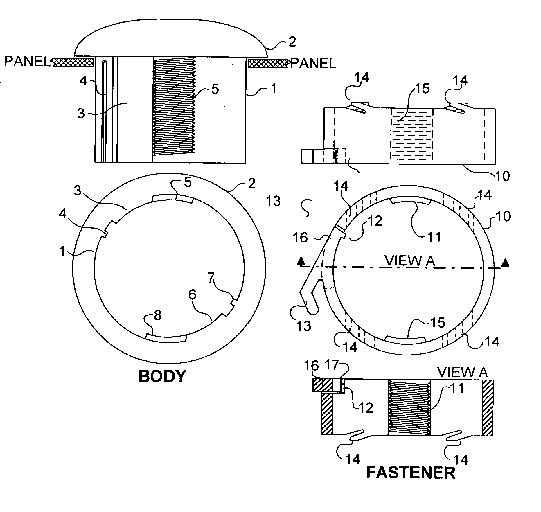
[0007] This invention consists of a method for allowing the rapid and secure connection of two generally cylindrical parts, a central body that is traditionally a threaded cylinder, with a mating piece that is traditionally a nut. The improvement described allows a quick insertion of the nut replacement piece to the point of engagement and a partial turn engagement of the nut replacement with the modified central body, and a final latching of the engaged parts to prevent undesired release through vibration or creep. Accomplishment of the improvement is by the use of partial screw segments to allow insertion of the nut replacement axially over the central body without rotation until the nut replacement is positioned where a rotation of the nut replacement will engage partial screw threads, acting as perpendicular shoulders to limit relative axial movement of the two members. This use of partial screw segments further allows enhancements such as positive locking of an installed fastener, controlled operator release of the fastener, and controlled clamping action. After engagement of the partial screw segments, a mechanism is provided to lock the rotational movement, preventing any further rotational or axial relative movement of the two bodies.
[0009] An interrupted screw is defined as “a screw with a slot or slots cut into the thread, especially one used in the breech of some guns permitting both engagement and release of the block by a partial turn of the screw” (The Collins English Dictionary© 2000 HarperCollins Publishers). The advantage of an interrupted screw is that a strong attachment can be made with this partial turn, and tolerances need not be more stringent than for a normal screw. For quick attachment of a module to a panel, for instance, the module body can have such an interrupted screw and the fastener has a matching thread pattern. The use of the fixed, partial turn of the fastener to fully engage the matching screw threads on the body allows the use of an alignment of the engaged screw thread shoulders to restrict the relative axial motion between the module and a fully engaged fastener, and a latching mechanism to prevent the relative radial movement thus keeping the fastener from disengaging. One implementation of this latching mechanism is a pawl and cog, to prevent the rotation of the body and fastener from unscrewing. A “pawl and cog” mechanism is defined as a lever arm (the pawl) with a face at the end that engages a protrusion or depression on the opposite member (the cog) to prevent further relative movement. This action provides a “snap” connection that positively locks the fastener and provides a more secure connection than a thread and nut.
[0010] Once the latching mechanism is engaged the fastener is prevented from unscrewing from the body. A method can be provided for the disengagement of the latching mechanism to allow easy unscrewing of the fastener form the body for module repair or replacement. In cases where removal of the module is to be prevented or made very difficult, the latching mechanism can be placed in an inaccessible location or can be only disengaged with a special tool.
[0011] The pitch of an ordinary interrupted screw provides a movement of the fastener axially along module body toward the panel. If this movement is not desired, the pitch of the screw threads can be made zero. There is often an advantage in allowing a yielding interface between the fastener and panel so that the tightening of the fastener against the body will force a compression of the yielding interface. This will increase the clamping force to the panel, which prevents the rotation of an installed module in the panel, avoids the appearance of loose components and prevents twisting of connecting wiring. The controlled tightening allows the reliable use of an elastometric seal to provide a water or gas tight seal.

Problems solved by technology

In large volume manufacture the time involved in screwing the nut is undesirable.
In addition, conditions like vibration can work the threaded fastener loose.
Lock washers cannot entirely solve this loosening problem and require additional time in the assembly.

Method used


Image

  • Latching quick-connect connector
  • Latching quick-connect connector
  • Latching quick-connect connector

Examples


Embodiment Construction

[0018] While the following discussion discusses the use of the fastening concept primarily as a means of attaching a module to a panel, the fastening process is equally adapted to most instances where traditionally a bolt and nut action has been used to accomplish the action of applying a fastener to a cylinder. Examples of such an action where this invention also has applicability is the attachment of a wheel to a hub, the attachment to studs mounted on a second body, and the attachment of two cylindrical bodies, one to another.

[0019] Directing attention to FIG. 1, a detailed drawing of a preferred embodiment is shown. There is a module body consisting of a head 2 and main body 1. The main body 1 is inserted through the panel as shown. There is a fastener 10 for mating with the main body 1. The main body 1 has a channel 3 and the fastener has a pawl 16 with a pawl face 12, and a section of screw 11. The channel 3 is wide enough to allow the screw section 11 to fit within the chann...


PUM


Abstract

A method is presented to allow a quick, positive attachment of a fastener to a module body. The module body and the fastener each have interrupted screw sections to connect with a partial turn. A latching mechanism, such as a pawl and cog arrangement, can provide a positive lock when the interrupted screw threads are fully engaged. A mechanism such as tab lever can be used to disengage the positive lock to easily remove the module. The controlled traverse over a known thread pitch allows the use of a compressible face on the fastener with a fixed compression and a repeatable, tight connection.

Description

BACKGROUND OF THE INVENTION [0001] 1. Field of the Invention [0002] This invention generally relates to a fastener. More particularly the invention relates to a quick-mount locking system for rapid and secure joining of two bodies. [0003] 2. Description of the Related Art [0004] There are many requirements for a rapid and secure joining of a fastener to the body to be fastened. One area of such requirement is the attachment of component modules to a panel. The following discussion emphasizes that requirement but the invention is a more general method of the quick and secure fastening of devices with many broad applications outside this particular application described in detail. [0005] Traditionally, components such as speakers, lights, and piezoelectric elements that are to be panel-mounted are enclosed in a module with a decorative head in front of the panel and a body inserted through the panel and secured by a threaded fastener. The use of the threaded fastener has several disad...

Claims


Application Information

Patent Timeline
IPC IPC(8): F16B39/32F16B37/08F16B25/00
CPCF16B37/085F16B39/32
Inventor DRYER, JOSEPH ERNEST
Owner DRYER JOSEPH E
Learn More