
Image matching device capable of performing image matching process in short processing time with low power consumption

Inactive Publication Date: 2005-10-06
SHARP KK
View PDF2 Cites 3 Cited by
  • Summary
  • Abstract
  • Description
  • Claims
  • Application Information

AI Technical Summary

Benefits of technology

[0019] Accordingly, it is an object of this invention to provide an image matching device, an image matching method and an image matching program product which can shorten the processing time and reduce the power consumption.

Problems solved by technology

Specifically, in an application of the personal authentication technologies to the portable terminals lacking a sufficiently large battery capacity, the reduction in power consumption as well as the shortening the time required for the matching process is a crucial problem.
Therefore, the problem is posed that an excessively large processing time and power are consumed.
As understood from this, the conventional matching method poses the problem that the total number of searches, i.e., the search amount is excessively large and so is the required processing amount, resulting in an excessively large consumption of both the processing time and power.

Method used


Image

  • Image matching device capable of performing image matching process in short processing time with low power consumption
  • Image matching device capable of performing image matching process in short processing time with low power consumption
  • Image matching device capable of performing image matching process in short processing time with low power consumption

Examples


first embodiment

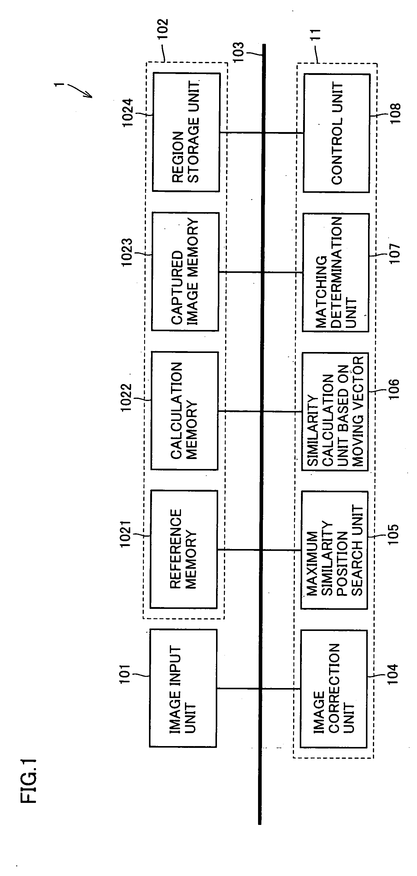
[0034] Referring to FIG. 1, an image matching device according to a first embodiment includes an image input unit 101, a memory 102 corresponding to a memory 624 or a fixed disc 626 (FIG. 3), a bus 103 and a matching processing unit 11.

[0035] Matching processing unit 11 includes, an image correction unit 104, a maximum similarity position search unit 105, a similarity calculation unit 106 based on a moving vector (hereinafter referred to as the similarity calculation unit), a matching determination unit 107 and a control unit 108. Each part of matching processing unit 11 implements the function thereof by executing a corresponding program.

[0036] Image input unit 101 includes a fingerprint sensor and outputs fingerprint image data corresponding to a fingerprint read by the fingerprint sensor. The fingerprint sensor may be any one of optical, pressure and electrostatic capacity types.

[0037] Memory 102 includes a reference memory 1021 for storing a reference image, a calculation mem...

second embodiment

[0106] Each processing function of image matching device 1 described in the first embodiment is implemented with a program. According to the second embodiment, the program is stored in a computer-readable recording medium.

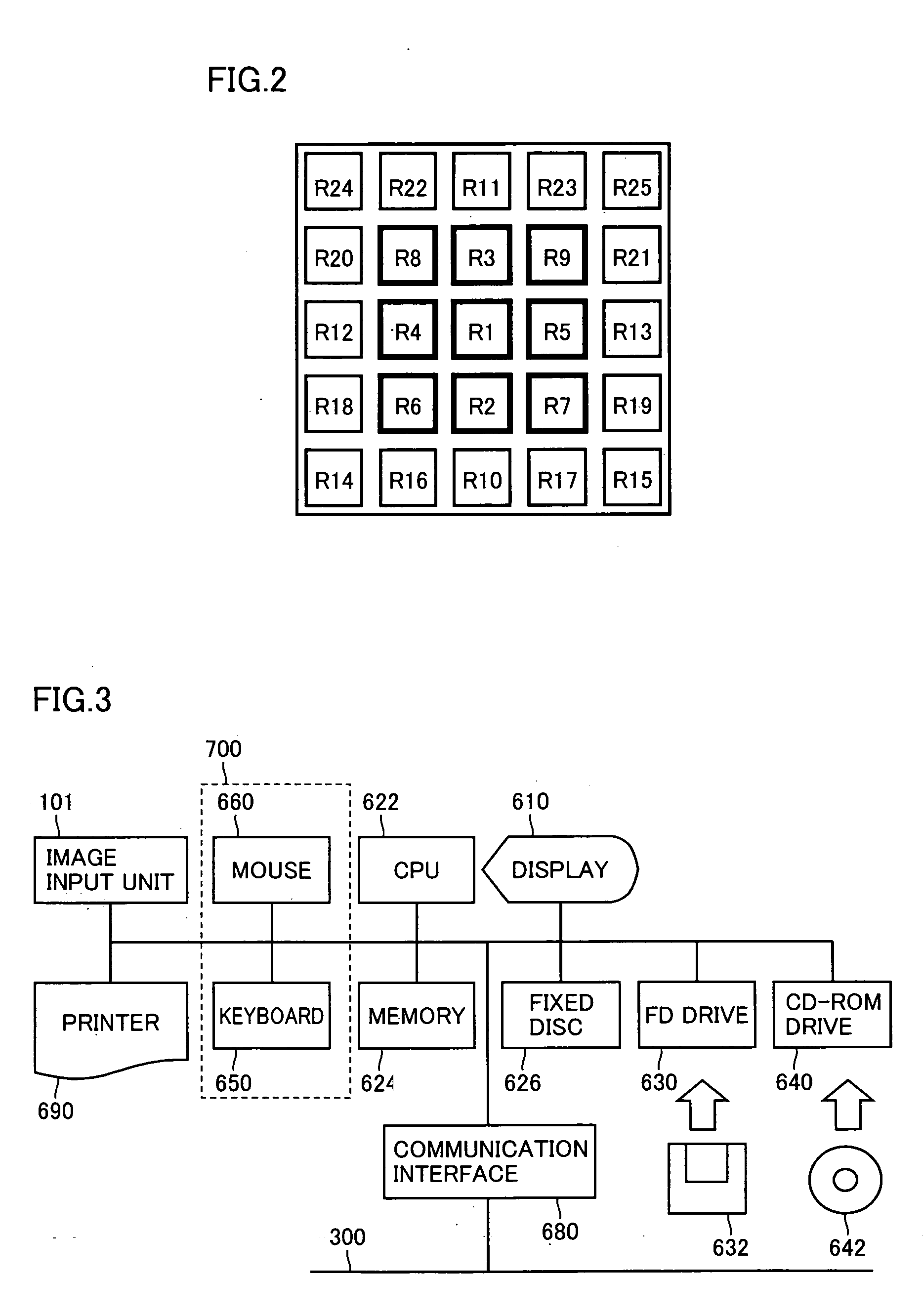
[0107] In this embodiment, a memory required for computer processing shown in FIG. 2 such as a memory 624 may be used as a program medium. As an alternative, a recording medium is removably mounted on an external memory of the computer so that the program can be read from the recording medium through the external memory. The external memory is a magnetic tape device (not shown), an FD drive 630 or a CD-ROM drive 640. The recording medium, on the other hand, is a magnetic tape (not shown), a FD 632 or a CD-ROM 642. In any case, the program stored in each recording medium can be accessed and executed by a CPU 622. As another alternative, the program is read in all cases from the recording medium and loaded into a predetermined program storage region shown in FIG. 2 ...


PUM


Abstract

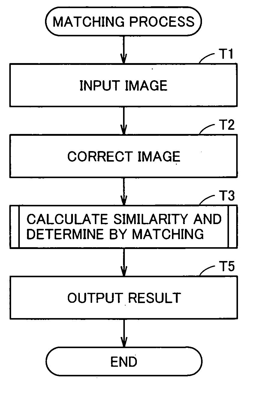
An image matching device capable of matching two images performs the following processes in order to shorten a processing time and reduce power consumption. Template matching is performed between a first image and a second image using a predetermined partial image of the first image, and the similarity between the two images is calculated. The similarity thus obtained is compared with a predetermined threshold. Only upon determination that the similarity obtained and the predetermined threshold neither coincide not fail to coincide with each other, the partial image used for template matching is gradually increased until the similarity and the predetermined threshold come to coincide or fail to coincide with each other. Then, template matching is performed again and the similarity between them is calculated.

Description

[0001] This nonprovisional application is based on Japanese Patent Application No. 2004-098038 filed with the Japan Patent Office on Mar. 30, 2004, the entire contents of which are hereby incorporated by reference. BACKGROUND OF THE INVENTION [0002] 1. Field of the Invention [0003] The present invention relates to an image matching device, an image matching method and an image matching program product. In particular, the present invention relates to an image matching device, an image matching method and an image matching program product for matching two images with each other. [0004] 2. Description of the Background Art [0005] Several methods of matching fingerprint images have been proposed. [0006] Japanese Patent Laying-Open No. 2003-323618, for example, discloses an image matching device employing the matching method described below. Specifically, in the image matching device disclosed in this publication, a fingerprint image to be matched is divided into a plurality of partial r...

Claims


Application Information

Patent Timeline
IPC IPC(8): G06T7/00G06K9/00G06K9/64
CPCG06K9/00087G06K2009/6213G06K9/6203G06V40/1365G06V10/7515G06V10/759
Inventor ITOH, YASUFUMIYUMOTO, MANABUONOZAKI, MANABU
Owner SHARP KK
Learn More