Eureka AIR delivers breakthrough ideas for toughest innovation challenges, trusted by R&D personnel around the world.

Methods and systems for laser based real-time structured light depth extraction

a laser-based, structured light technology, applied in the direction of instruments, catheters, applications, etc., can solve the problems of incandescent light with poor photonic efficiency, single camera for both broadband light detection and calculation to determine the depth of the object to be extremely fast, etc., to achieve easy focus, improve photonic efficiency, and improve efficiency

Inactive Publication Date: 2005-10-06
THE UNIV OF NORTH CAROLINA AT CHAPEL HILL
View PDF25 Cites 170 Cited by
  • Summary
  • Abstract
  • Description
  • Claims
  • Application Information

AI Technical Summary

Benefits of technology

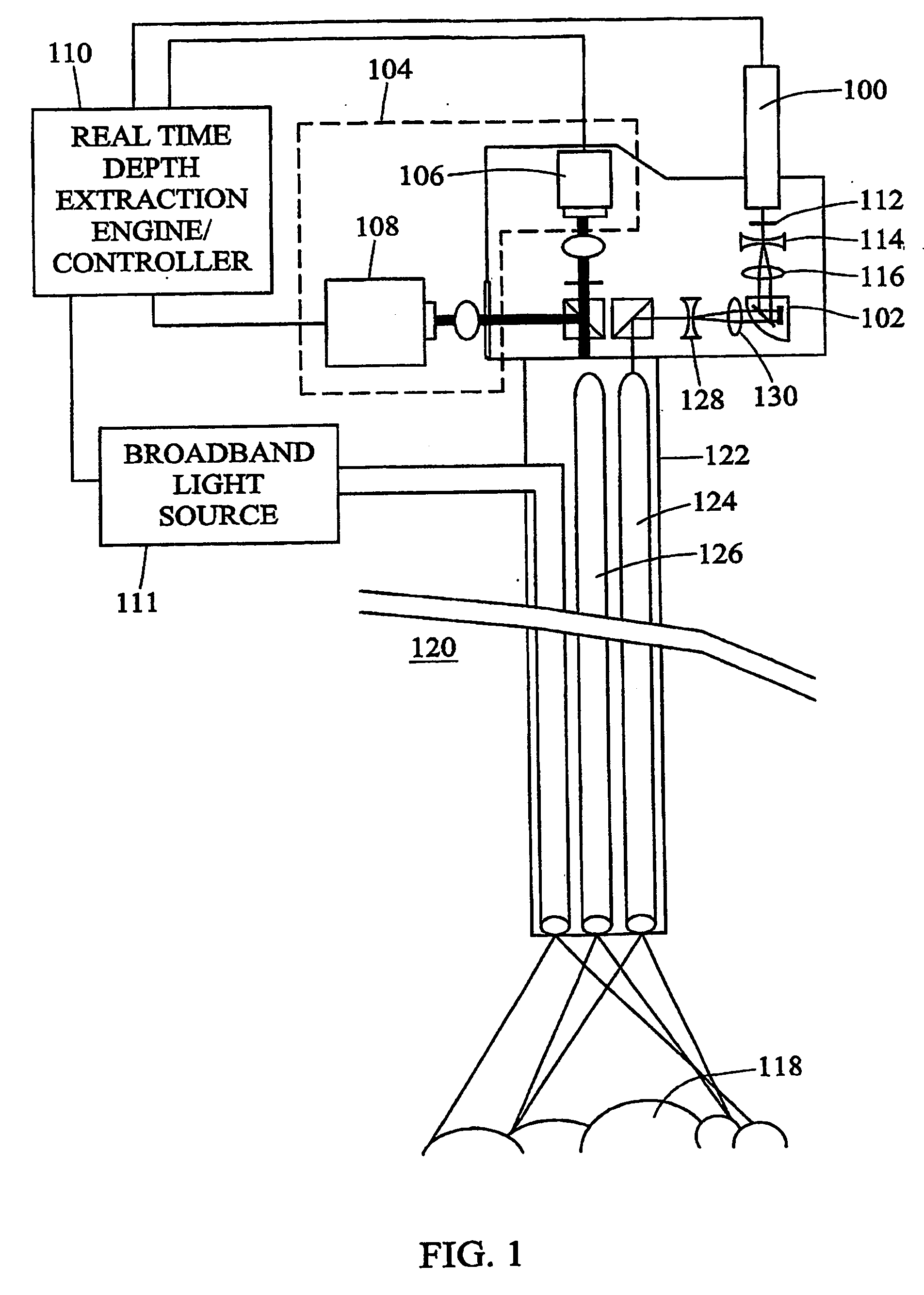
[0009] Using a laser light source rather than an incandescent lamp provides advantages over conventional real-time structured light depth extraction systems. For example, laser-based real-time structured light depth extraction systems have been shown to have better photonic efficiency than incandescent-lamp-based real-time structured light depth extraction systems. In one test, the efficiency of a laser-based real-time structured light depth extraction system for endoscopic surgery was shown to have 30% efficiency versus 1% efficiency for incandescent light. This increase in efficiency may be due to the fact that a laser-based real-time structured light depth extraction system may not require a colliminator in series with the laser light beam before contacting the pattern generator. In addition, a laser can be easily focused to fit within the diameter of the optical path of an endoscope, while the focal width of an incandescent light beam is limited by the width of the filament, which can be greater than the width of a conventional endoscope. Using a laser for real-time structured light depth extraction in an endoscopic surgical environment may thus allow a smaller diameter endoscope to be used, which results in less trauma to the patient.
[0011] In an alternate implementation of the invention, rather than using a laser light source and a separate display, the present invention may include using a self-illuminating display, such as an organic light emitting (OLE) display. Using an OLE display decreases the number of required optical components and thus decreases the size of the real-time structured light depth extraction system. Patterns can be generated and projected simply by addressing the appropriate pixels of the OLE display.
[0013] Accordingly, it is an object of the present invention to provide improved methods and systems for real-time structured light depth extraction in an endoscopic surgical environment.

Problems solved by technology

In addition, the calculations to determine the depth of the object are required to be extremely fast.
While this conventional structured light depth extraction system may be effective in some situations, incandescent light has poor photonic efficiency when passed through the optics required to image surfaces inside a patient in an endoscopic surgical environment.
Another problem with this conventional structured light depth extraction system is that using a single camera for both broadband light detection and depth extraction is suboptimal since the pixel requirements for broadband light detection are greater than those required for depth extraction, and the required frame speed is greater for depth extraction than for broadband light detection.
Using a single camera results in unnecessary data being acquired for both operations.
The additional data acquired when using a single camera for both broadband light detection and depth extraction increases downstream memory storage and processing speed requirements.

Method used


Image

  • Methods and systems for laser based real-time structured light depth extraction
  • Methods and systems for laser based real-time structured light depth extraction
  • Methods and systems for laser based real-time structured light depth extraction

Examples


Embodiment Construction

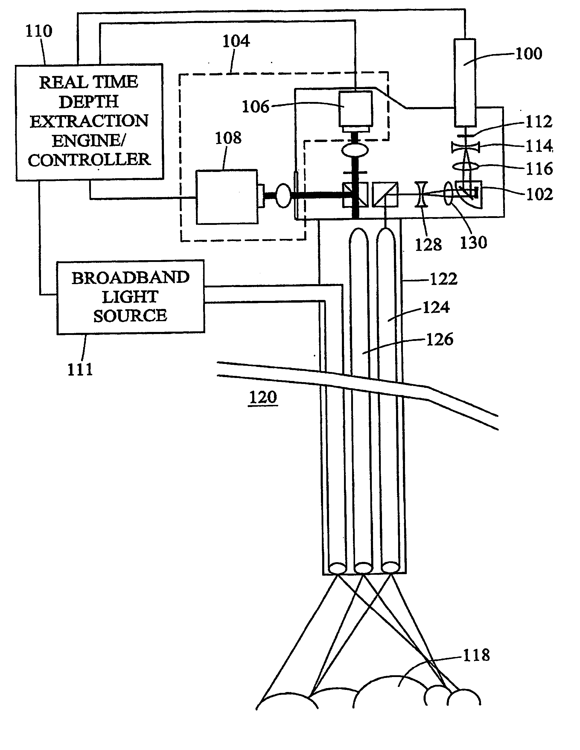
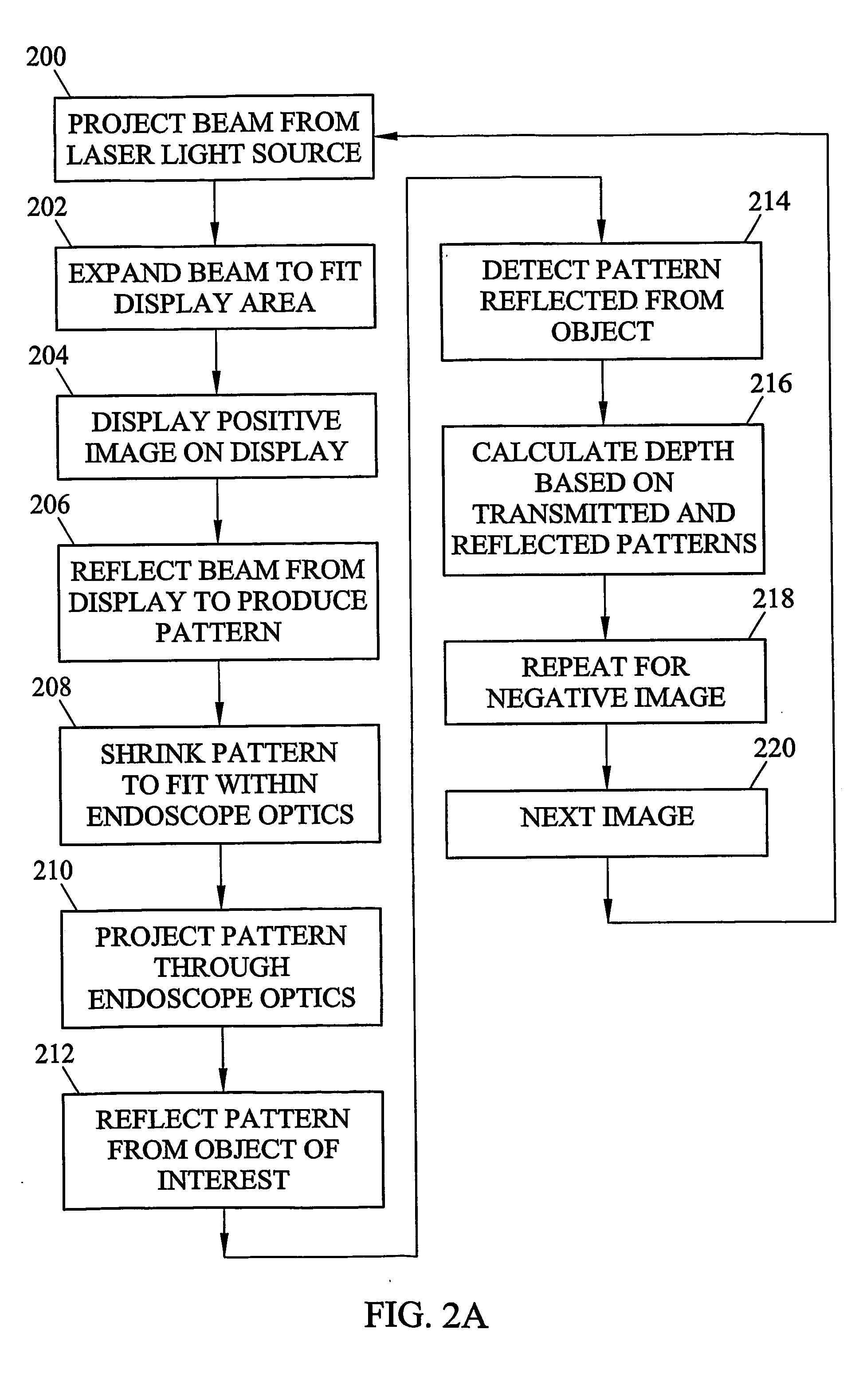
[0023]FIG. 1 illustrates a system for laser-based real-time structured light depth extraction according to an embodiment of the present invention. Referring to FIG. 1, the system includes a laser light source 100, a pattern generator 102, a detector 104 including cameras 106 and 108 and a real-time depth extraction engine / controller 110. Laser light source 100 may be any suitable laser light source, such as a laser diode. In a preferred embodiment of the invention, when extracting depth for surfaces within the human body, laser light source 100 comprises a narrowband light source of appropriate frequency for a reduced penetration depth and reduced scattering of light by the surfaces being imaged. The frequency range of light emitted from laser light source 100 may be in the visible or non-visible frequency range. A green light source has been found to be highly effective for imaging human and animal tissue. By reducing scattering and penetration of light, features in reflected struc...


PUM


Abstract

Laser-based methods and systems for real-time structured light depth extraction are disclosed. A laser light source (100) produces a collimated beam of laser light. A pattern generator (102) generates structured light patterns including a plurality of pixels. The beam of laser light emanating from the laser light source (100) interacts with the patterns to project the patterns onto the object of (118). The patterns are reflected from the object of interest (118) and detected using a high-speed, low-resolution detector (106). A broadband light source (111) illuminates the object with broadband / light, and a separate high-resolution, low-speed detector (108) detects broadband light reflected from the object (118). A real-time structured light depth extraction engine / controller (110) based on the transmitted and reflected patterns and the reflected broadband light.

Description

RELATED APPLICATIONS [0001] This application claims the benefit of U.S. Provisional Patent Application Ser. No. 60 / 386,871, filed Jun. 7, 2002, the disclosure of which is incorporated herein by reference in its entirety.GOVERNMENT INTEREST [0002] This invention was made with U.S. Government support under Grant No. DABT63-93-C-0048 from the Advanced Research Projects Agency (ARPA) and under grant number ASC8920219 awarded by the National Science Foundation. The U.S. Government has certain rights in the invention.TECHNICAL FIELD [0003] The present invention relates to methods and systems for real-time structured light depth extraction. More particularly, the present invention relates to methods and systems for laser-based real-time structured light depth extraction. BACKGROUND ART [0004] Structured light depth extraction refers to a method for measuring depth that includes projecting patterns onto an object, detecting reflected patterns from the object, and using pixel displacements i...

Claims


Application Information

Patent Timeline
IPC IPC(8): A61B1/04A61B5/107G01B11/25G02B23/24
CPCA61B1/042A61B5/1076H04N13/0253G02B23/2484G06T7/0057G01B11/2536G06T7/521H04N13/254A61B1/0605
Inventor ACKERMAN, JERMY D.KELLER, KURTIS P.
Owner THE UNIV OF NORTH CAROLINA AT CHAPEL HILL
Why Eureka
Eureka Blog
Learn More