
Beam reshaping unit for an illumination system of a microlithographic projection exposure apparatus

a technology of exposure apparatus and illumination system, which is applied in the direction of photomechanical apparatus, printers, instruments, etc., can solve the problems of unsatisfactory light intensity distribution in these regions, and achieve the effect of better light energy distribution

Inactive Publication Date: 2005-10-06
CARL ZEISS SMT GMBH
View PDF29 Cites 8 Cited by
  • Summary
  • Abstract
  • Description
  • Claims
  • Application Information

AI Technical Summary

Benefits of technology

The present invention provides a beam reshaping unit for illumination systems used in microlithographic projection exposure apparatuses. The beam reshaping unit has a flexible usability for various illumination settings. It includes a beam reshaping element with a curved surface that can introduce refractive power to concentrate light onto individual regions in the pupil plane or to distribute it over a wider area. The curved surface has a curved non-conical region that can influence the distribution of light energy. The beam reshaping unit can also have a concave or convex curved outer region to achieve an additional lens effect. The design of the beam reshaping unit allows for a smooth transition of light energy to different regions in the pupil plane. The invention also provides a method for designing the beam reshaping unit using a curved surface and a curve segment. Overall, the invention provides a more flexible and effective beam reshaping unit for microlithographic projection exposure apparatuses.

Problems solved by technology

Common to the known axicon systems is the fact that, although the illuminated regions in the pupil plane have the desired geometries, the light intensity distributions within these regions are not satisfactory.

Method used


Image

  • Beam reshaping unit for an illumination system of a microlithographic projection exposure apparatus
  • Beam reshaping unit for an illumination system of a microlithographic projection exposure apparatus
  • Beam reshaping unit for an illumination system of a microlithographic projection exposure apparatus

Examples


Embodiment Construction

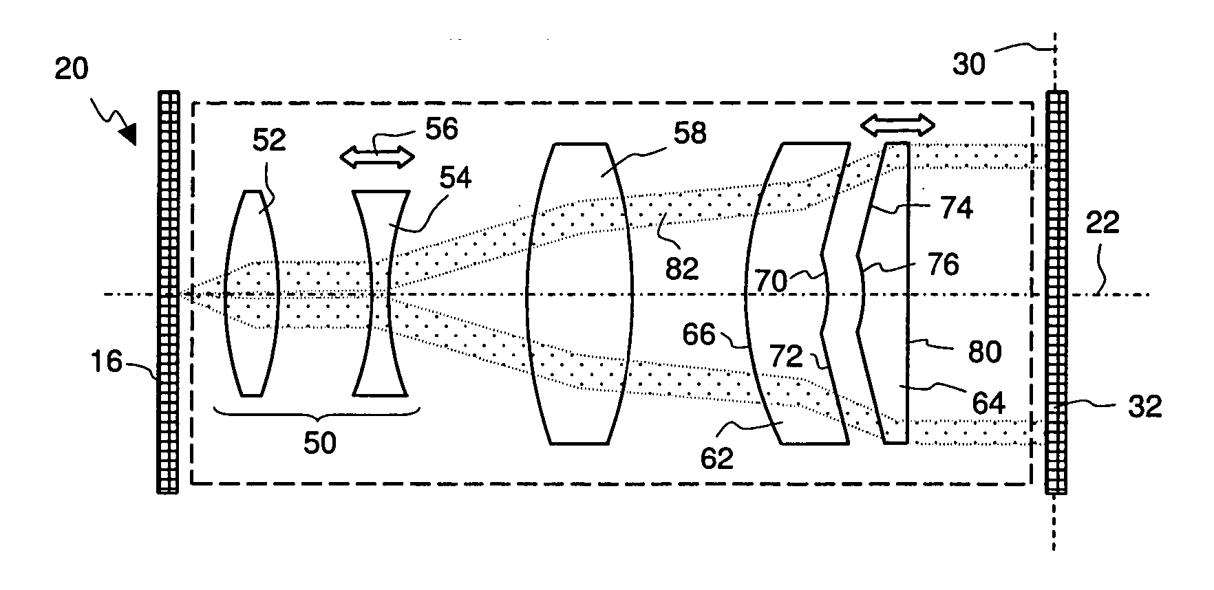
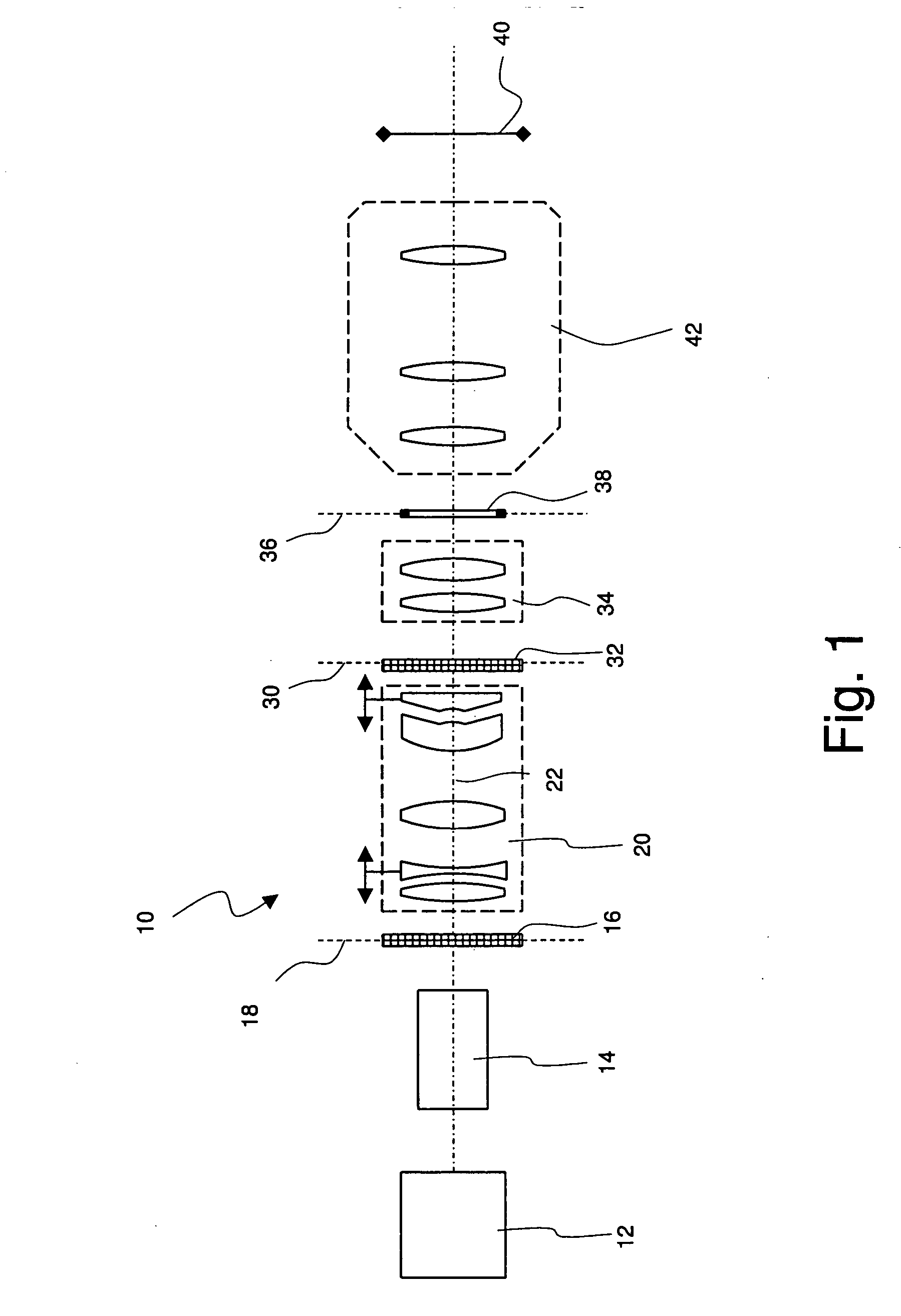
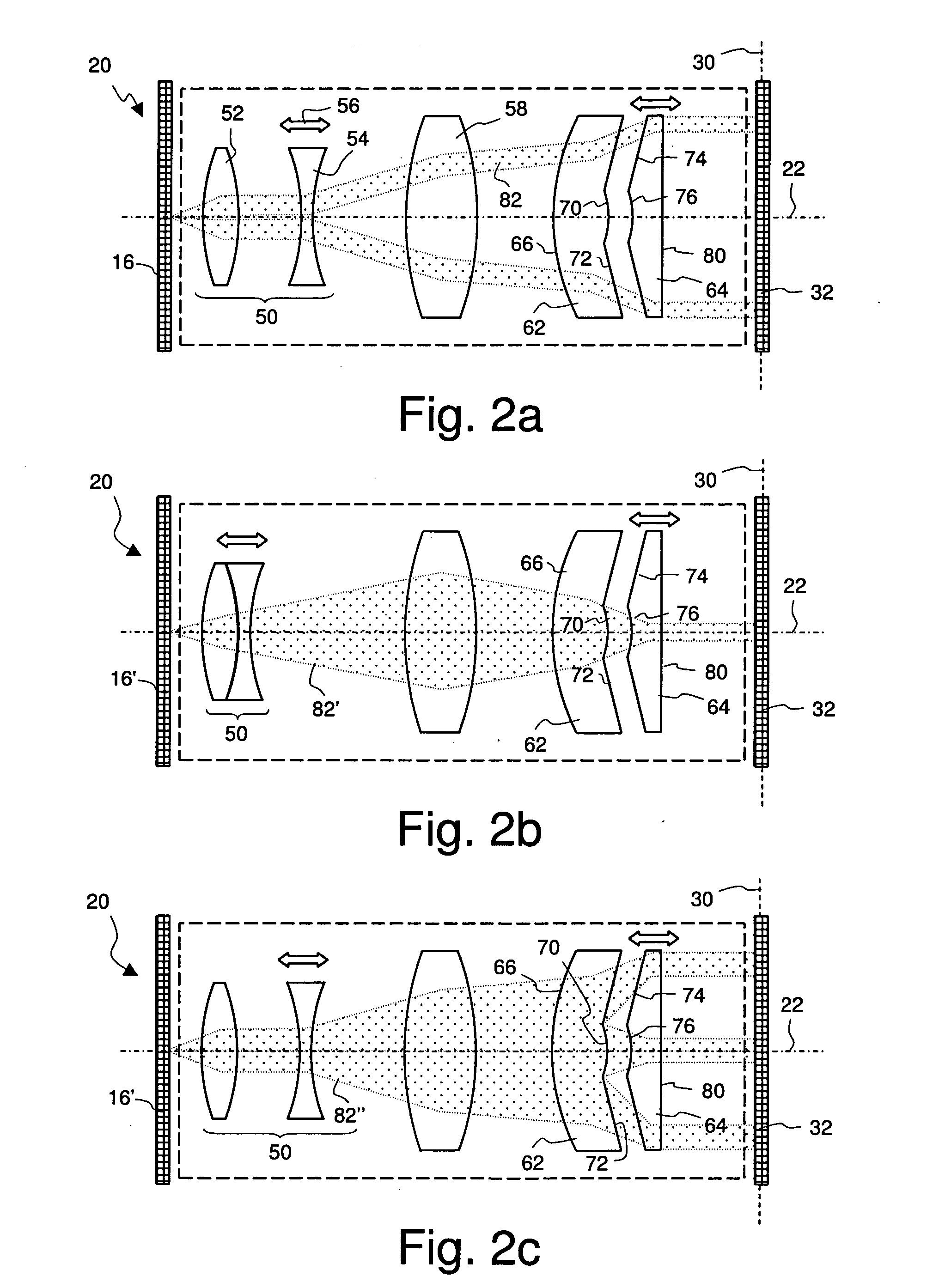
[0052]FIG. 1 shows in a simplified meridional section an illumination system that is denoted in its entirety by 10. The illumination system 10 comprises a light source 12 in the form of an excimer laser. The light source 12 generates monochromatic and strongly—but not completely—collimated light with a wavelength in the deep ultraviolet spectral range, e.g. 193 nm or 157 nm.

[0053] In a beam expander 14, which may be realized as an adjustable mirror arrangement, the light generated by the light source 12 is expanded into a rectangular and substantially parallel light bundle. The expanded light bundle then passes through a first optical raster element 16, which can be for example a diffractive optical element. Further examples of suitable raster elements are disclosed in U.S. Pat. No. 6,285,443 assigned to the applicant, the full disclosure of which being incorporated herein by reference. The first optical raster element 16 has the task of altering the angular distribution of the pro...


PUM

PropertyMeasurementUnit
angles of incidenceaaaaaaaaaa
wavelengthaaaaaaaaaa

Abstract

A beam reshaping unit for an illumination system (10) of a microlithographic projection exposure apparatus comprises a first beam reshaping element (62) having a first beam reshaping surface (68) and a second beam reshaping element having a second beam reshaping surface (74) which faces the first beam reshaping surface (68). The two beam reshaping surfaces (68; 74) are rotationally symmetrical with respect to an optical axis (22) of the beam reshaping unit. At least the first beam reshaping surface (68, 74) has a concavely or convexly curved region (70, 76).

Description

CROSS-REFERENCE TO RELATED APPLICATIONS [0001] This application claims priority of U.S. provisional patent application Ser. No. 60 / 531,436, filed Dec. 19, 2003.BACKGROUND OF THE INVENTION [0002] 1. Field of the Invention [0003] The invention relates to a beam reshaping unit for an illumination system of a microlithographic projection exposure apparatus. Such apparatuses are used to produce large-scale integrated circuits and other micro-structured components. [0004] 2. Description of Related Art [0005] In the production of micro-structured components, a plurality of structured layers is applied to a suitable substrate, which can be, for example, a silicon wafer. To structure the layers, these are first covered with a photosensitive resist which is sensitive to light of a particular wavelength range, e.g. light in the deep ultraviolet spectral range (DUV, deep ultraviolet). The wafer coated in this way is then exposed to light in a projection exposure apparatus. Such an apparatus com...

Claims


Application Information

Patent Timeline
Patent Type & Authority Applications(United States)
IPC IPC(8): G03B27/54G03F7/20
CPCG03F7/70183G03F7/70108
Inventor SINGER, WOLFGANGDEGUENTHER, MARKUSKUERZ, BIRGITEGGER, RAFAELWANGLER, JOHANNESMAUL, MANFRED
Owner CARL ZEISS SMT GMBH
Learn More