Electronic component having micro-electrical mechanical system
a mechanical system and micro-electric technology, applied in the direction of instruments, semiconductor/solid-state device details, device material selection, etc., can solve the problems of difficult to keep the mechanical strength of the si substrate, difficult to form the opening in a predetermined size in a predetermined position on the upper surface of the substrate accurately, and little design freedom
- Summary
- Abstract
- Description
- Claims
- Application Information
AI Technical Summary
Problems solved by technology
Method used
Image
Examples
first embodiment
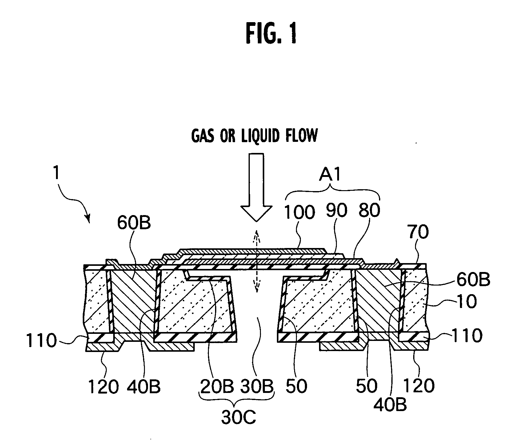
[0027] In FIG. 1A, a structure of an MEMS electronic component 1 according to the first embodiment is shown. As shown in FIG. 1A, the MEMS electronic component 1 according to the first embodiment includes an MEMS element (an electrical mechanical element) A1, which has a movable portion in an upper surface (or a first electrode) of a silicon substrate 10. The first embodiment illustrates a piezoelectric device, as the MEMS element A1, which can be used as a thin film bulk acoustics resonator (FBAR), various sensors, etc. The piezoelectric device has a structure where a piezo-electric film 90 is sandwiched between the upper electrode 100 and a lower electrode (or a second electrode) 80. The piezo-electric film 90 moves in the vertical direction shown by a broken-line arrow, and in the in-planar direction of the substrate plane.
[0028] The MEMS electronic component 1 according to the first embodiment has a cavity 30C, which penetrates from an upper surface (or a first surface) to a lo...
second embodiment
[0055] A structure of a MEMS electronic component 3 according to the second embodiment is shown in FIG. 5.
[0056] As shown in this drawing, like the MEMS electronic component 1 according to the first embodiment, the MEMS electronic component 3 according to the second embodiment includes a MEMS element A2 with a movable portion on the upper surface of a silicon substrate 11. The MEMS electronic component 3 also includes a cavity 31B, which penetrates between the upper surface and the lower surface of the silicon substrate 11, in the region corresponding to the mechanical movable portion of the MEMS element A2. Further, the MEMS electronic component 3 includes an electric conduction plug 61B penetrating between the upper surface and the lower surface of the silicon substrate 11, which is assigned as a lead electrode of the MEMS element A2. The variations in structure from the MEMS electronic component 1 according to the first embodiment are as follows. First, unlike the first embodime...
third embodiment
[0069] The third embodiment is a modification of the second embodiment. Although the structure of the MEMS electronic component has almost the same structure as the one shown in FIG. 5, the space for movement for the MEMS element and the subsequent trench formation step of forming the cavity portion are different.
[0070] Steps of manufacturing the trench 31A, which is the characterizing portion according to the third embodiment, is shown in FIG. 7A and FIG. 7B. In addition, FIG. 7A and FIG. 7B show cross sectional views at 7B-7B line of a plan view shown in FIG. 7C.
[0071] As shown in FIG. 7A, a shallow trench 21 is formed for securing the space for movement of the MEMS element in the silicon substrate 11. Next, resist 200 is patterned to form an etching mask, and an etching residual pattern 210 in the shape of a convex is formed in the trench 31A using this etching mask, as shown in FIG. 7B. With the presence of this etching residual pattern 210 in the shape of a convex, the amount...
PUM
 Abstract
Description
Claims
Application Information
 - R&D
- Intellectual Property
- Life Sciences
- Materials
- Tech Scout
- Unparalleled Data Quality
- Higher Quality Content
- 60% Fewer Hallucinations
Browse by: Latest US Patents, China's latest patents, Technical Efficacy Thesaurus, Application Domain, Technology Topic, Popular Technical Reports.
© 2025 PatSnap. All rights reserved.Legal|Privacy policy|Modern Slavery Act Transparency Statement|Sitemap|About US| Contact US: help@patsnap.com


