
Apparatus and method for controlling the amount of trash in lint

a technology of lint cleaning and trash removal, applied in the direction of mechanical treatment, mechanical fibre separation, textiles and paper, etc., can solve the problems of loss of lint to the producer, inability of existing lint cleaning machines to provide a method to vary the amount of cleaning the machine performs, and damage to the fibers

Inactive Publication Date: 2005-10-06
GVILI MICHAEL E +3
View PDF15 Cites 11 Cited by
  • Summary
  • Abstract
  • Description
  • Claims
  • Application Information

AI Technical Summary

Benefits of technology

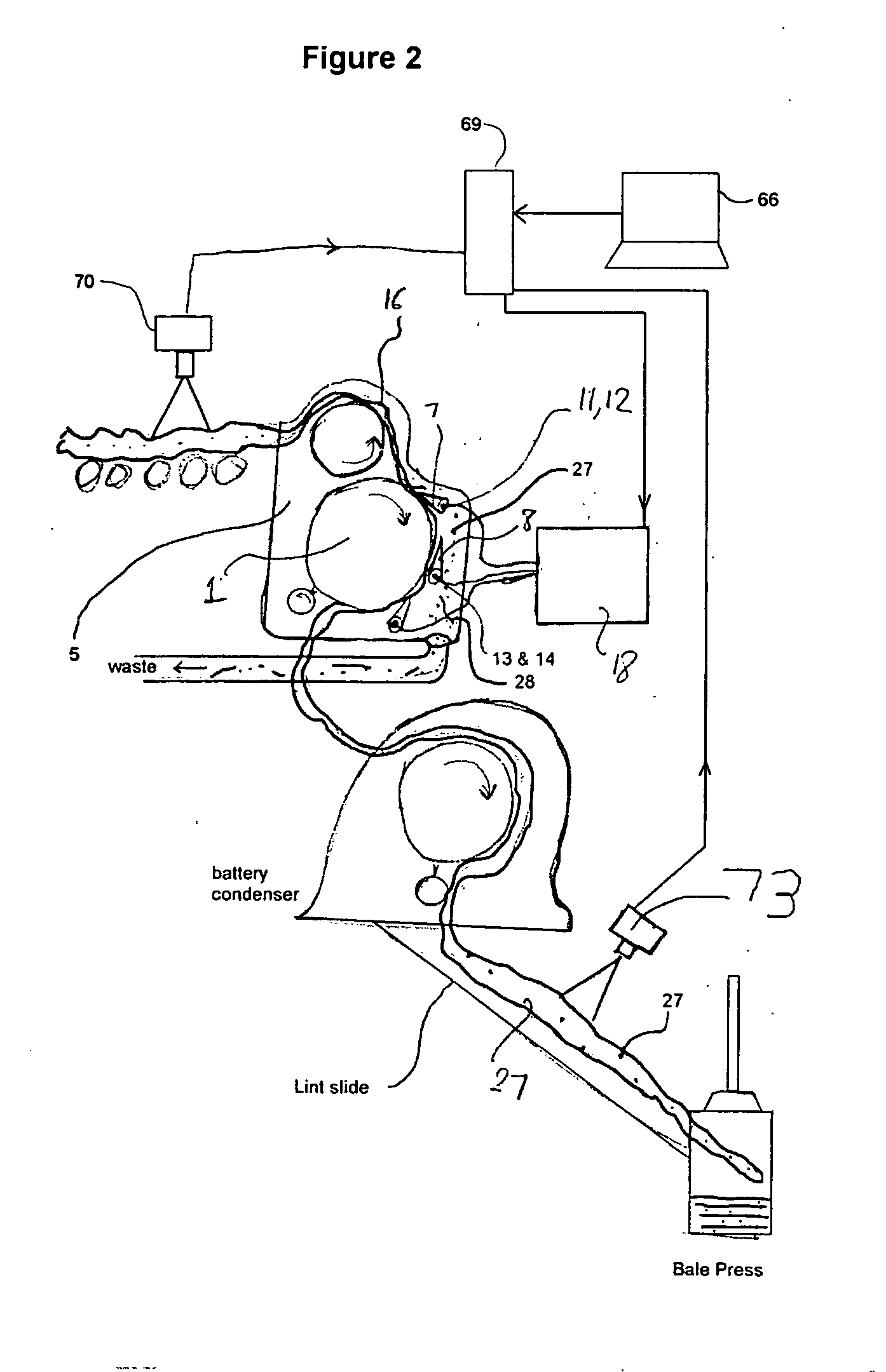
[0008] The inventive system is represented in FIG. 1, but is not limited to the components of FIG. 1. It consists of an imaging device which can estimate the amount of trash existing in the lint before it enters the lint cleaner, and a second imaging device at the exit point of the lint cleaner or at the final station when the bat is packaged into a bale of cotton. An estimate of the amount of trash in the cotton during process is calculated continuously; several times for each bale. The results are then averaged to obtain a moment by moment condition of cleanliness before and after the cotton is cleaned. This occurs in a timely fashion so the lint cleaner process algorithm can be performed. This invention also includes movable grid bars, typically either movable by hand, or by the use of motors, which may be manually or automatically controlled to engage and disengage one or more grid bars. These grid bars are equipped with electrical motors, or pneumatic or hydraulic actuators, or other remotely controlled actuators, referred to here as grid bar actuators. The actuators enable the invention's lint cleaner controller to position the grid bars against the rotating battery of saws, referred to herein as the engaged position, or to separate them so they do not take part in the cleaning process, referred here as the disengaged position. While the grid bar is in the engaged position it is functioning as a trash-removing surface which removes trash from the cotton being cleaned. Any one of the grid bars can be independently repositioned by the actuators, at any moment during the cleaning process. A grid bar can be moved to the disengaged position where the surface of its cleaning edge is no longer in contact with the lint or the trash. In this position, the grid bar is not being used as cleaning device, and in that position it no longer cause any loss of lint or damage to it.
[0009] The grid bars may also be equipped with a lint-retaining member such as retention bars or retention brushes or both, as shown in FIGS. 6 and 7. Both the retention bar and the retention brush keep the lint in contact with the saws when the grid bar is in the disengaged position. The retention bar or brush prevents the possibility of dislodging the lint from the saw by the fast flowing air. The dislodging of lint from the saws is due to the centrifugal forces applied by the spinning of the saws.

Problems solved by technology

It has been demonstrated that during the cleaning process the grid bars also remove some usable lint from the rotating saws, causing a loss of lint to the producer.
Existing lint cleaners do not provide a method to vary the amount of cleaning the machine performs.
The disadvantage of Anthony's invention is that it does not remove sheet metal edges from contacting the lint, thus continuing to cause damage to the fibers.
Also, Anthony's invention is complex to build and operate.

Method used


Image

  • Apparatus and method for controlling the amount of trash in lint
  • Apparatus and method for controlling the amount of trash in lint
  • Apparatus and method for controlling the amount of trash in lint

Examples


Embodiment Construction

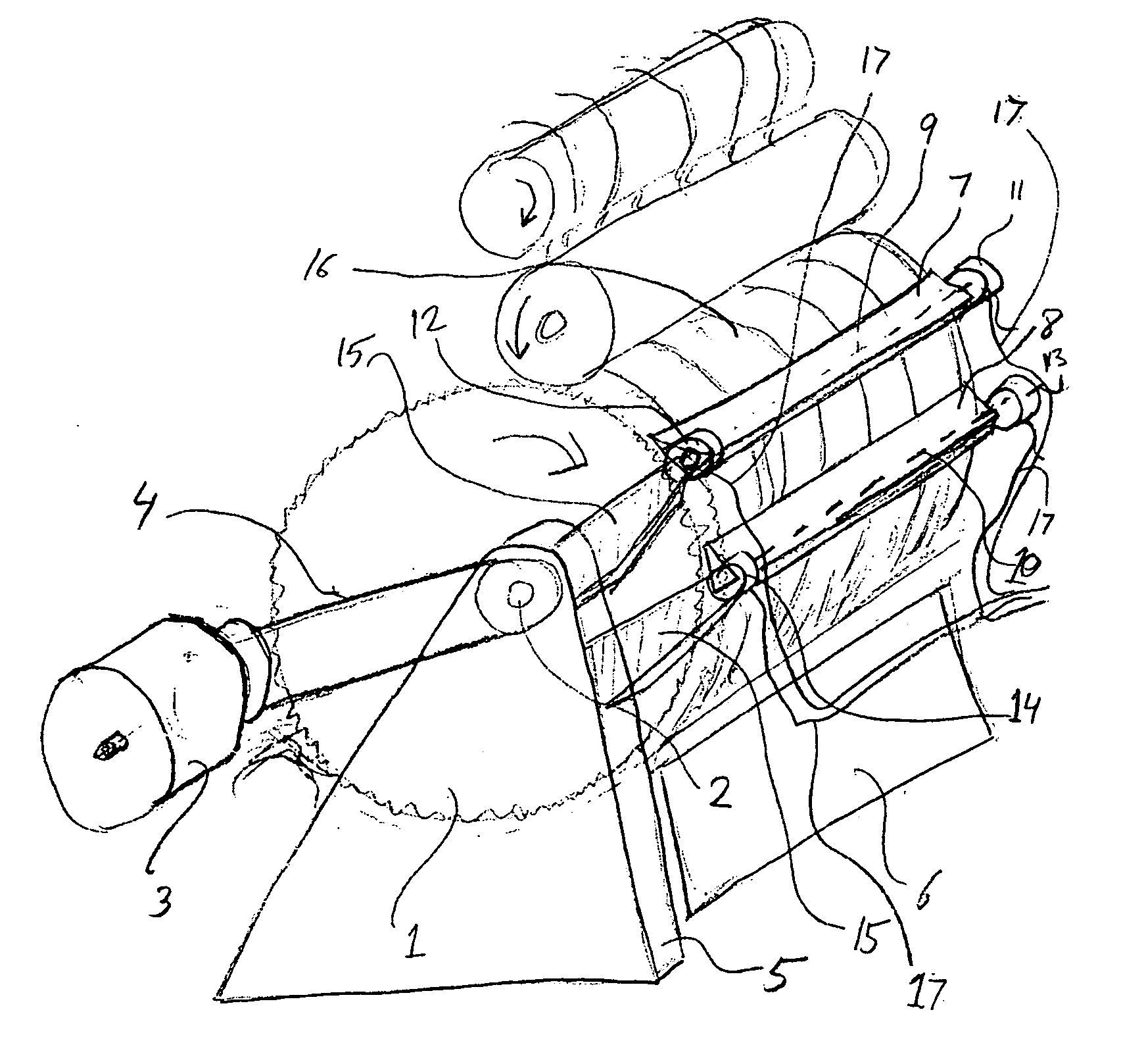
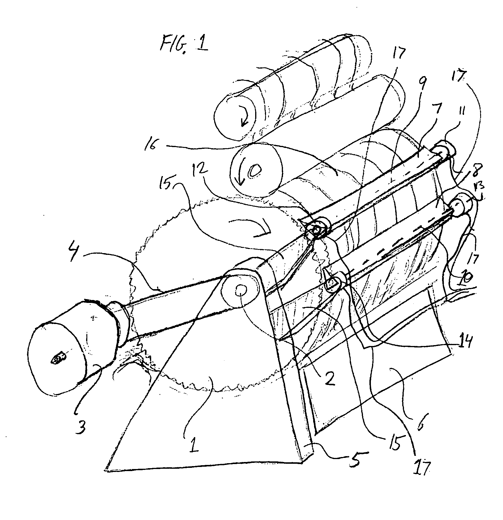
[0024] The invention of lint cleaning machine in a cotton processing facility such as cotton gin, is illustrated in FIG. 1. The lint cleaner is comprised of a battery of saws 1 containing multiple, round, narrow saws of the typical diameter ranging from 16 to 24 inches. All of the saws are spinning around the same axis 2 and driven by a single motor or mechanical drive or gear 3 through the shaft or belt 4. The motor or gear 3 is mounted on a stationary frame 5 of the lint cleaner, which also supports the housing and other components of the lint cleaner 6. On the frame 5 are several mounted grid bars 7 and 8 as shown in FIG. 1. The invention applies to the use of one or more grid bars in a lint cleaning machine. Each of the grid bars is mounted on a pivoting shaft 9 and 10. Electric motors 11, 12, 13 and 14, such as step motor with or without a gear, rotary solenoids or other actuators are coupled to the shafts, to controllably rotate the shafts. These grid bars are mounted respecti...


PUM

PropertyMeasurementUnit
diameteraaaaaaaaaa
distanceaaaaaaaaaa
thresholdaaaaaaaaaa

Abstract

An apparatus and algorithm for controlling the operation of a lint cleaner in a cotton gin having motorized grid bars, in which any one of the grid bars can be positioned in an engaged or disengaged position. When the grid bar is in the engaged position it functions as a lint cleaning instrument on a lint cleaning machine. When it is in the disengaged position it does not participate in the active cleaning process.

Description

FIELD OF THE INVENTION [0001] This invention relates to the lint cleaning process and machinery used in cotton processing facilities such as cotton gins. The invention provides an apparatus and methods for controlling the amount of cleaning performed during the lint cleaning process, thus optimizing the cotton producer's income by reducing waste and damage to the lint. BACKGROUND OF THE INVENTION [0002] Lint cleaning machines, used in cotton processing facilities, employ stationary grid bars to remove trash, leaves and other particles from the lint during the cleaning process, as described in W. S. Anthony and William D. Mayfield; Cotton Ginners Hand Book United States Department of Agriculture; Agricultural Research Service Agricultural Handbook Number 503; Copyright December 1994 . The lint cleaner uses a bank of circular saws to propel a thin preconditioned layer of lint through the lint cleaning machine. The lint fibers, which may contain leaf fragments, seed fragments, sticks a...

Claims


Application Information

Patent Timeline
Patent Type & Authority Applications(United States)
IPC IPC(8): D01B1/04
CPCD01B1/04
Inventor GVILI, MICHAEL E.MEZHEBOVSKY, STANISSLAVNORTHERN, MARTIN JAMESLUCUS, ROBERT LYNN
Owner GVILI MICHAEL E
Learn More