Direct forming of non-textile fabric elements from thermoplastic pellets or the like

a technology of thermoplastic pellets and non-textile fabric elements, which is applied in the direction of instruments, other domestic articles, transportation and packaging, etc., can solve the problems of phase forming itself not being utilized, the forming process is also somewhat limited, and the type of products are limited, so as to achieve significant efficiency and reduce time, labor and scrap costs

Inactive Publication Date: 2005-09-29
OCONNOR GREGORY W +1
View PDF6 Cites 13 Cited by
  • Summary
  • Abstract
  • Description
  • Claims
  • Application Information

AI Technical Summary

Benefits of technology

[0007] The instant invention as described herein overcomes the shortcoming of the above-referenced polymer forming processes, and includes the molding, in place, of interconnected elements into a non-textile type fabric using solid-phase molding techniques, preferably from conventionally produced polymer pellets. This combination is referred to as direct forming. The interconnected elements are molded directly into their assembled positions in a continuous web, or other shape, of the resulting fabric. Forming the elements into their final assembled structure, that is interconnec

Problems solved by technology

These forming processes are also somewhat limited in that there are limitations on the type of products that can be made.
These limitations become more important when the desired product made of the plastic is required to be flexible, durable, strong and easily assembled, such as a non-textile fabric.
While solid phase forming c

Method used


Image

  • Direct forming of non-textile fabric elements from thermoplastic pellets or the like
  • Direct forming of non-textile fabric elements from thermoplastic pellets or the like
  • Direct forming of non-textile fabric elements from thermoplastic pellets or the like

Examples


first embodiment

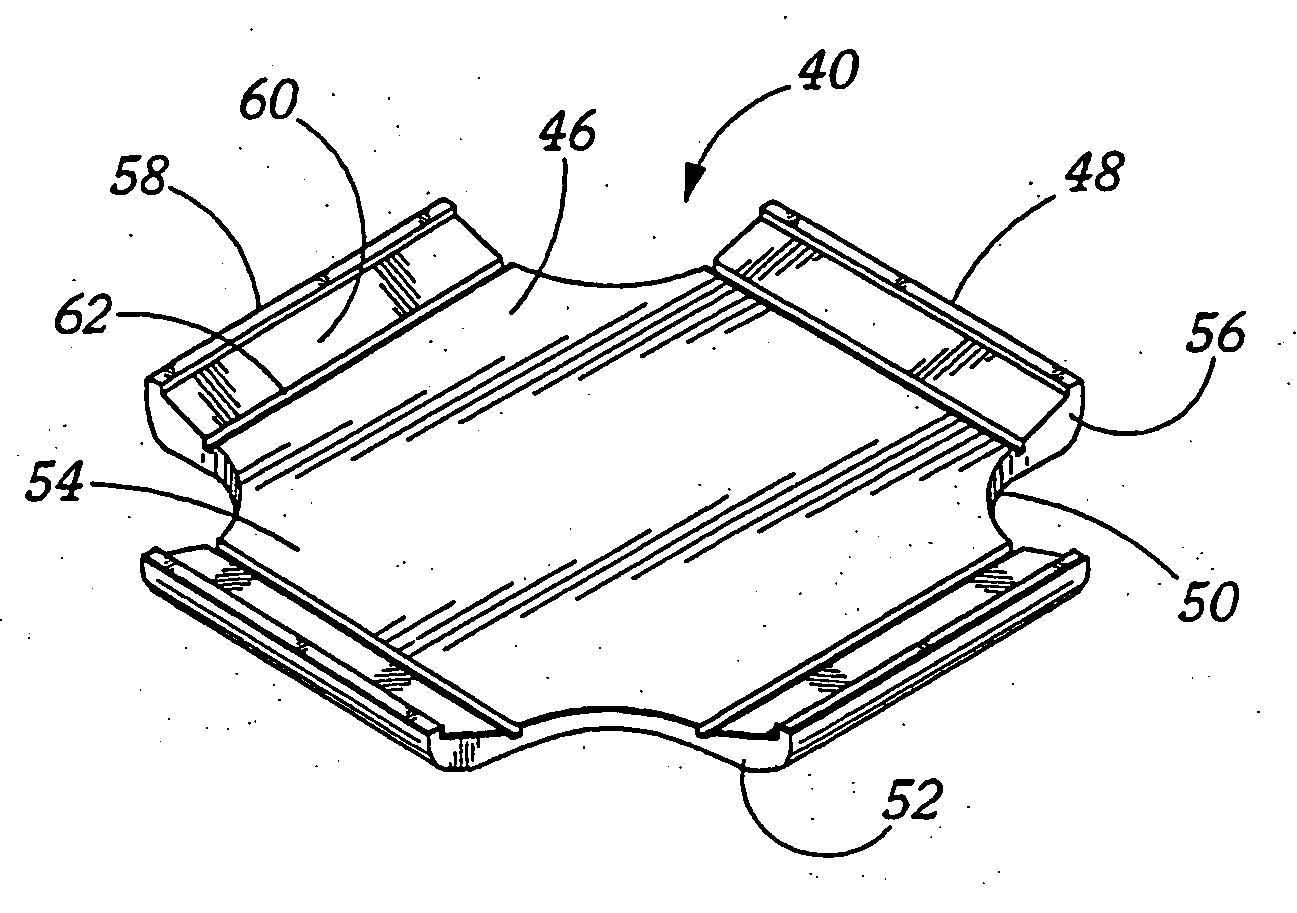
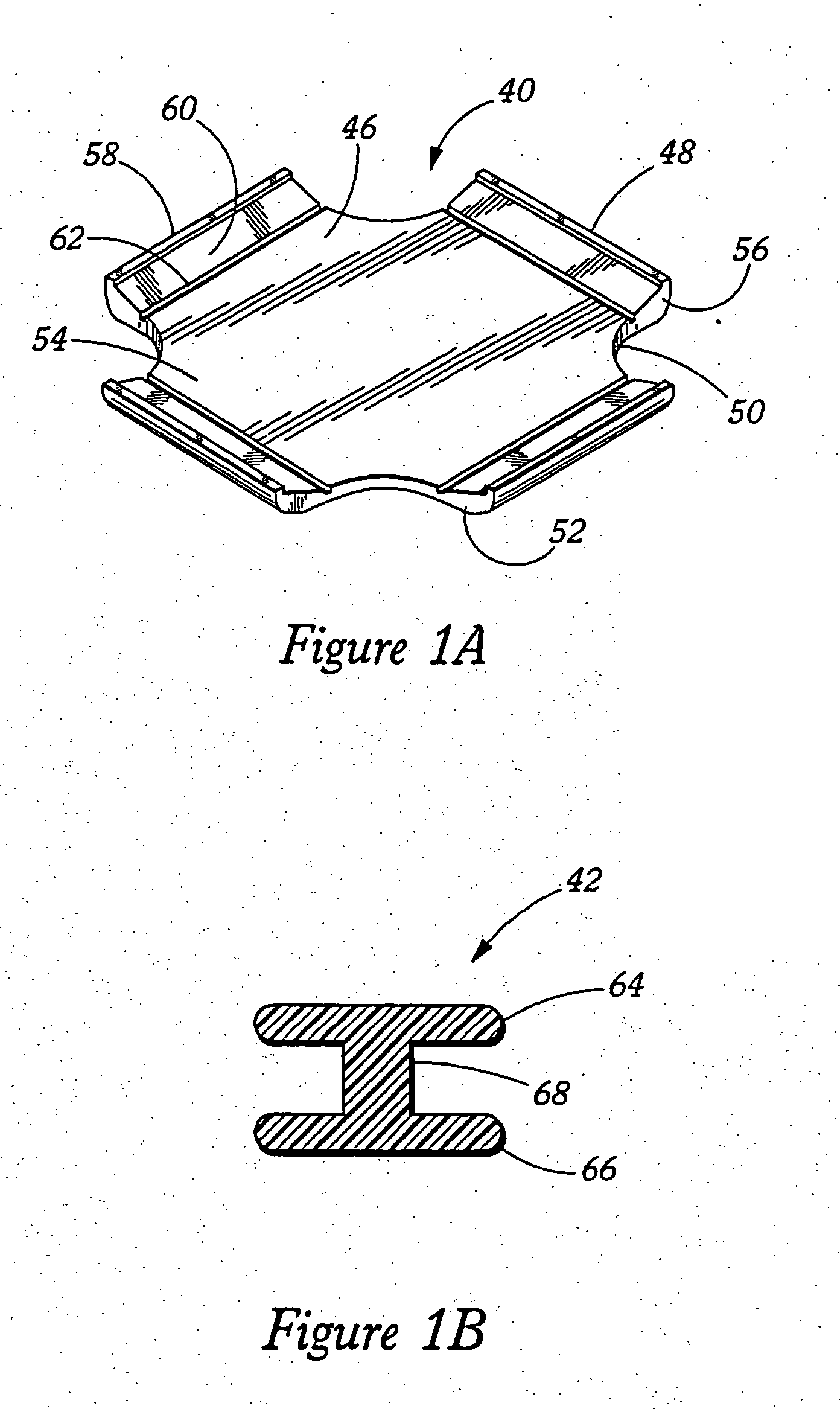
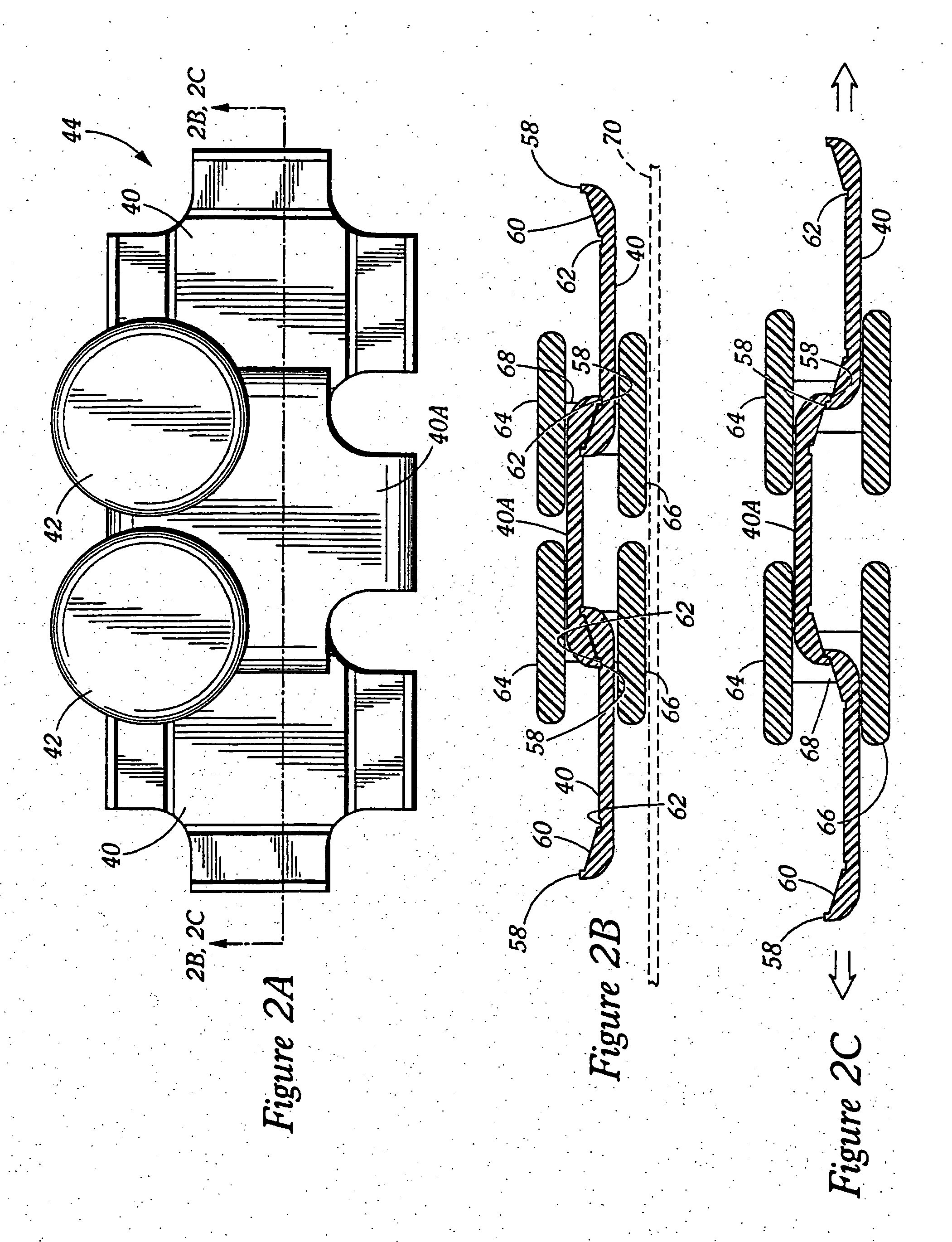
[0116] Another embodiment of the linkable elements for forming the non-textile fabric using the process of the present invention is shown in FIGS. 14A, 14B, 15 and 16. FIGS. 14A and 14B show top and bottom views of the linkable element 130 made by the solid phase forming process. The structure is similar to that of the first embodiment described herein in FIGS. 1-3, however, there are no cam surfaces on the edges 132 of the plate elements for counter-engagement, and the rivet 134 is integrally formed with the plate element. The straight edges 132 engage one another to keep the elements from moving laterally apart. In this embodiment, only one shape of element 130 is required and is able to be interlinked in a “legs up” (FIG. 14B) and a “legs down” (FIG. 14A) orientation using the direct forming process as described above. The plate element 130 with the integrally formed rivet 132 is formed in one single phase forming process step (with the appropriate mold cavity shape and analogous...

second embodiment

[0123] At operation 508, which is the application of heat to the pellets, the solid phase forming process actually begins. The application of heat to the pellets is only necessary if the heat generated by the solid phase transformation of the pellet into the mold cavity is not sufficient to create the desired temperature in the pellet. In other words, if the heat generated by the transformation from its shape to that of the mold cavity due to the impact of the striker is not sufficient, as described above, supplemental heat may be necessary. The ultimate temperature to which the pellet should be heated is above the softening point but below the melting point of the particular polymer forming the pellet. After the heat management of the pellet has been performed, the actual solid phase transformation step is performed at operation 510. The solid phase forming step has been described in great detail above, and to reiterate the description above, it can be performed using the rollers a...


PUM

PropertyMeasurementUnit
Angleaaaaaaaaaa
Volumeaaaaaaaaaa
Speedaaaaaaaaaa

Abstract

An inventive solid phase forming process, and related structure, using conventional pelletized thermoplastic compositions to form the of a non-textile fabric by coining a single pellet or briquette of the polymer into an individual element in a single forming step. The steps of the process generally include: a) positioning a pellet in or adjacent to a mold cavity, and b) forcing the pellet into contact with the mold surfaces of the mold cavity to plastically deform the pellet to cause the pellet to adapt the shape of the mold cavity. The mold cavity has a shape to form the desired element, and its volume is substantially the same as the volume of the pellet. The forcing step or act preferably uses an energy and speed where the pellet superplastically deforms to substantially fill the volume of the mold cavity. This process is repeated with the particular element being formed in the appropriate order to form interconnected plates and rivets, as an example, with the final result being a non-textile fabric. The elements formed by the inventive process can have any of a variety of shapes, and can form base units for the formation of the non textile fabric of two, three or more elements. This inventive process eliminates the need to first form the pelletized polymer into a sheet or other type of preform prior to the forming of the final product.

Description

FIELD OF THE INVENTION [0001] This invention relates to a combination polymer processing and article manufacturing process, and more particularly relates to a method and process for creating uniquely shaped polymer elements in an interlinked structure. BACKGROUND [0002] The use of plastics has become pervasive in present-day products of all types. The processes by which plastics are formed into or integrated as specific elements with the products have been carefully developed to generally maximize the volume of product output and performance characteristics of the resulting plastic products. Typically, the polymer process is used to form an individual product or element, such as a packaging structure (plastic bottle) or an individual element of a larger article (gear member for a low power drive train, or a filament of thermoplastic for combining into yarn or synthetic textiles). [0003] The traditional and well-known plastic forming processes include, among others, injection molding...

Claims


Application Information

Patent Timeline
IPC IPC(8): B29C43/18B29C43/46F41H5/04G01B1/00
CPCB29C43/18Y10T428/17B29C65/028B29C65/58B29C65/605B29C65/606B29C66/435B29C66/8322B29C66/83413B29C2043/189B29C2043/3422B29C2043/465B29L2031/4842B29L2031/729B29L2031/768F41H5/0471B29C43/46B29C66/1142B29C66/12421B29C66/71B29C66/8242B29C66/8244B29K2023/065B29K2055/02B29K2069/00
Inventor O'CONNOR, GREGORY W.GREGG, JAMES S.
Owner OCONNOR GREGORY W
Why Eureka
Try Eureka