Moving body measuring apparatus

a moving body and measuring device technology, applied in the direction of instruments, gymnastic exercise, using reradiation, etc., can solve the problems of insufficient image processing, complex image processing, and inability to photograph the reflective marker positioned in the region of interest at high contrast, and achieve the effect of high precision

Active Publication Date: 2005-09-29
YOKOHAMA RUBBER CO LTD
View PDF9 Cites 88 Cited by
  • Summary
  • Abstract
  • Description
  • Claims
  • Application Information

AI Technical Summary

Benefits of technology

[0007] An object of the present invention is to provide a moving object measuring apparatus that overcomes the above problems of the prior art and is capable of finding movement information (such as movement velocity, movement direction, and rotation rate) of a moving body, such as a golf club head or a golf ball that moves while accompanying a spin, with high precision.
[0009] According to the present invention, the irradiation light source, the camera, and the optical member are adjustably arranged so that the angle at which irradiation light outgoes from a boundary surface of the optical member substantially coincides with the angle at which light reflected by the reflection marker is incident upon the boundary surface of the optical member. Accordingly, light can be uniformly irradiated onto the reflection marker, and the reflection marker can be photographed with a high contrast, unlike conventional measuring apparatuses. Measurements of complex motion can therefore be performed at high precision by using a configuration that is simpler than configurations employed by conventional measuring apparatuses. In particular, extremely important information, namely information on the position, orientation, and the like of an impact surface of a golf club head immediately before a golf ball is struck can be accurately found when selecting a golf club head as the moving body.

Problems solved by technology

The light reflected by the reflective marker positioned in the region of interest thus cannot be photographed at high contrast, and it becomes necessary to perform complex image processing in order to correct the photographed image.
Further, depending upon the circumstances, image processing may not be enough and the movement information of the moving body thus cannot be found.

Method used


Image

  • Moving body measuring apparatus
  • Moving body measuring apparatus
  • Moving body measuring apparatus

Examples


Embodiment Construction

[0032] A moving body measuring apparatus and a moving body measuring method of the present invention are explained in detail below based on preferred embodiments shown in the accompanying drawings.

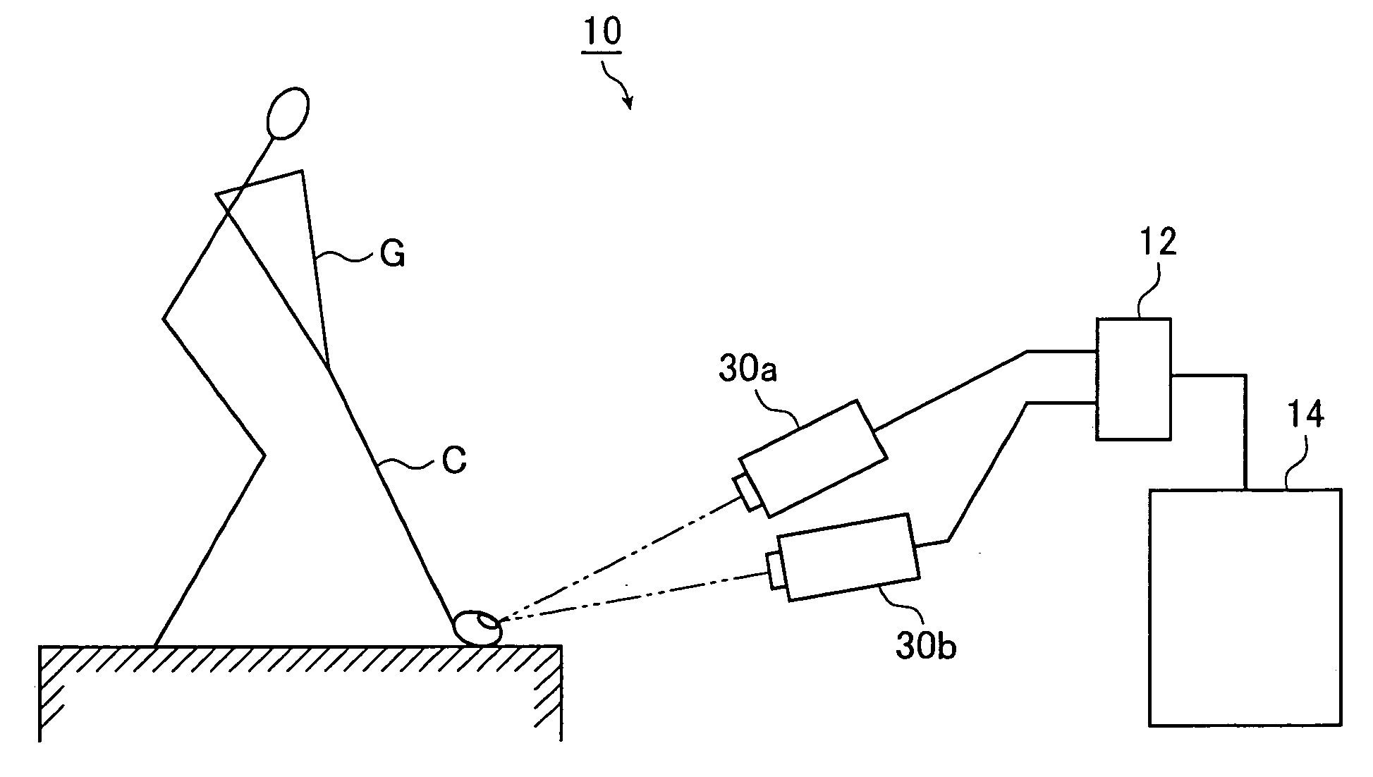
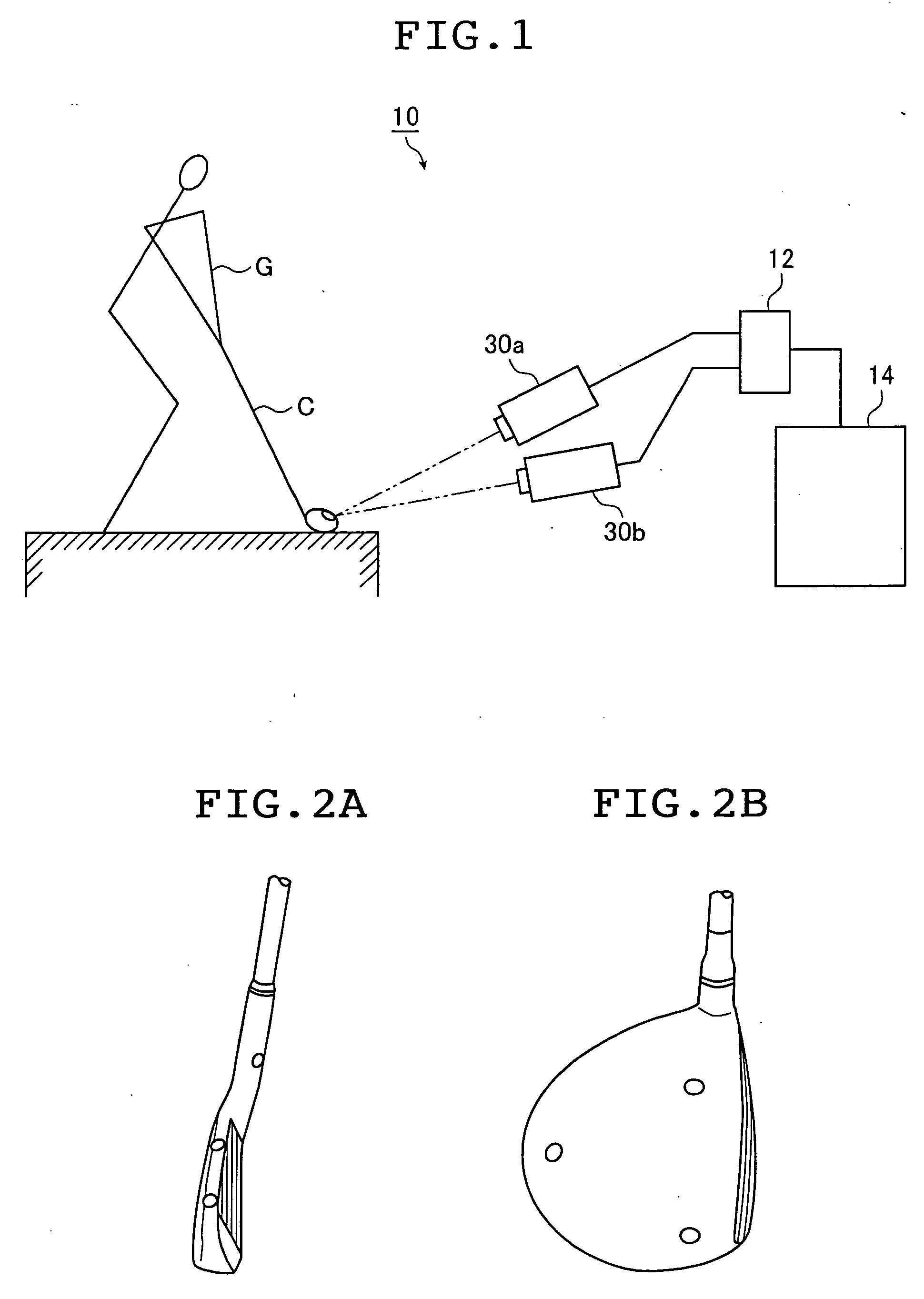
[0033]FIG. 1 is a side view that schematically shows an embodiment of a moving body measuring apparatus of the present invention. A golf club head is used here as a moving body to be measured.

[0034] A moving body measuring apparatus (hereinafter called a head measuring apparatus) 10 shown in FIG. 1 is an apparatus that measures movement information of a golf club head before and after the golf club head strikes a golf ball when a golfer G grips a golf club C and swings the golf club C to strike the golf ball.

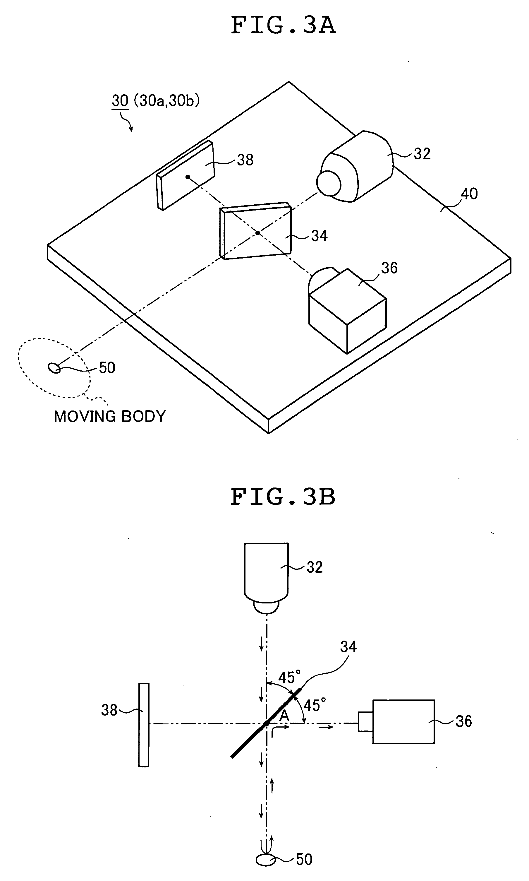
[0035] The head measuring apparatus 10 includes irradiation and photographing portions 30a and 30b that photograph a golf club head from two different directions and have substantially the same construction of optical devices such as cameras and irradiation light sources. The head m...


PUM


Abstract

A moving body measuring apparatus of the invention measures movement information of a moving body as an object to be measured. The apparatus has an optical member having a boundary surface on which light is incident, the optical member being adapted to transmit light entering the boundary surface from one side and to reflect light entering the boundary surface from the other side; an irradiation light source that emits light toward the optical member and irradiates light outgoing from the optical member onto the moving body; a camera that photographs via the optical member an image of light reflected from a reflection marker provided on a surface of the irradiated moving body; and a movement information computation portion that computes movement information for the moving body based on the image of the light reflected by the reflection marker and photographed by the camera, wherein arrangement of the irradiation light source, the camera, and the optical member is adjusted such that an outgoing angle of the irradiation light outgoing from the boundary surface substantially coincides with an incoming angle at which the light reflected by the reflection marker enters the boundary surface.

Description

BACKGROUND OF THE INVENTION [0001] The present invention relates to a moving body measuring apparatus that measures movement information of a moving body, such as the movement velocity, the movement direction, and the orientation of a golf club head immediately prior to a golf club striking a golf ball during a golf swing, and the initial velocity, movement direction, and spin rate of a golf ball immediately after being struck by the golf club. [0002] Methods and apparatuses for finding movement information, such as movement velocity and rotation amount by providing a plurality of cameras along a path of a moving body, and photographing the moving body to measure the movement thereof (motion and behavior) have been heretofore proposed. [0003] For example, JP 8-304020 A discloses a moving body movement-accuracy measuring apparatus that measures the amount of movement and the direction of movement of a moving body simultaneously, and performs evaluation of angular deviations of the mo...

Claims


Application Information

Patent Timeline
IPC IPC(8): A63B69/36A63B69/00G01B11/00G01N21/25G01P3/36G01P3/38G01P3/40G01P3/68G01S7/481G01S17/58G03B15/00G06T1/00
CPCA63B24/0003A63B69/3614A63B2220/806A63B2220/807G01S17/58G01P3/40G01P3/68G01S7/481G01P3/38A63B24/0021A63B2024/0028A63B2220/805G01P3/36
Inventor SAEGUSA, HIROSHI
Owner YOKOHAMA RUBBER CO LTD
Why Eureka
Try Eureka