
Stent delivery system with diameter adaptive restraint

a technology of adaptive restraint and stent, which is applied in the field of medical devices and methods, can solve problems such as potential benefiting unit costs, and achieve the effect of facilitating insertion and broader applicability

Inactive Publication Date: 2005-09-22
BIOSENSORS INT GROUP
View PDF99 Cites 78 Cited by
  • Summary
  • Abstract
  • Description
  • Claims
  • Application Information

AI Technical Summary

Benefits of technology

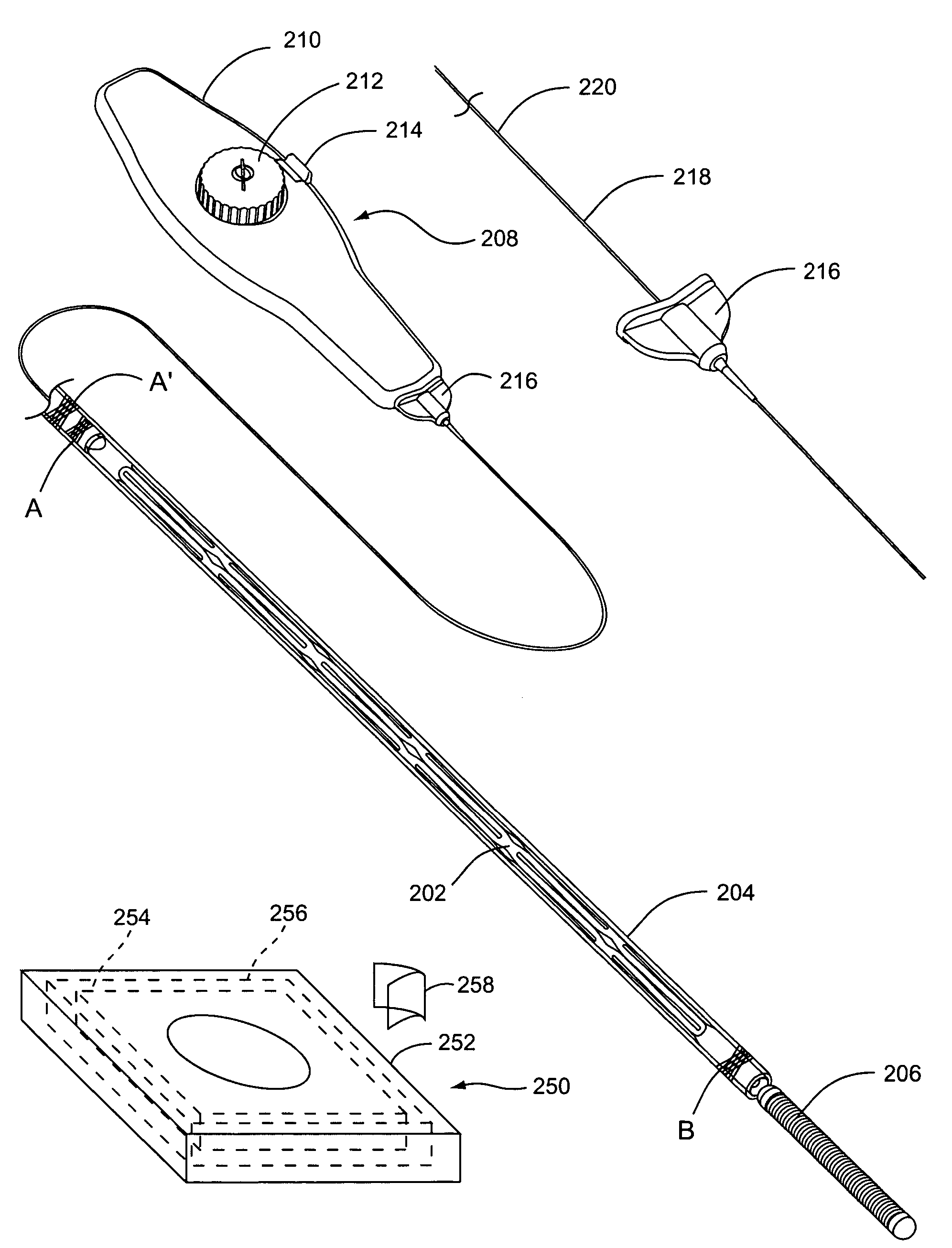
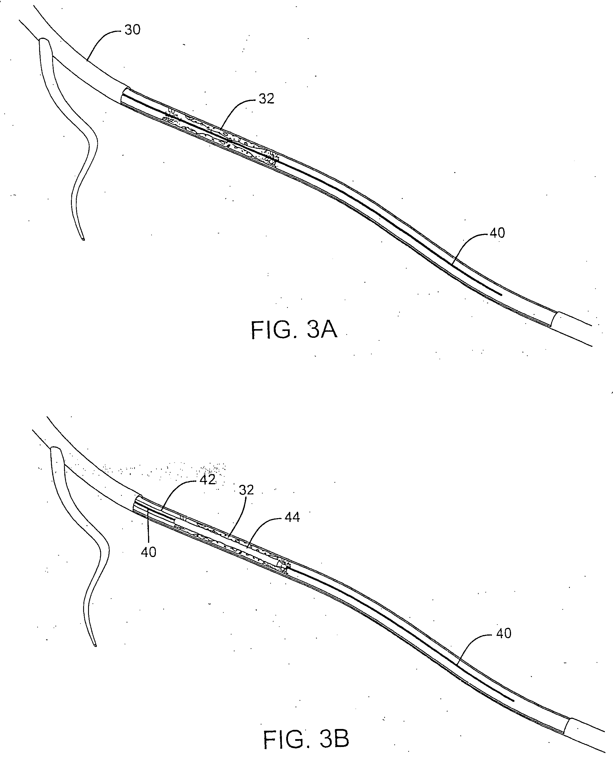
[0010] The present invention offers a stent delivery system in which a restraint holding a stent in position for deployment is adapted to collapse radially upon withdrawal from the stent. This diameter adaptive restraint enables the system to operate in a highly space efficient manner. Furthermore, it opens possibilities for efficient design and construction—these considerations potentially benefiting unit cost. Still further, the diameter adaptive restraints may be incorporated into delivery systems offering different functional characteristics. Though the invention may have broader applicability, the exemplary variations of the invention described herein employ a stationary outer tube or sleeve and an interior wire (whether it is a corewire or another member) to actuate the restraint to draw it off of the stent to release the same upon achieving intended positioning at a target site.
[0013] By actuating the interior member (e.g., by withdrawing the same or by a physical shortening, such as by a heat-activated shape memory plastic or alloy wire). Simple withdrawal of the inner member will deploy the stent. Yet, a more user-friendly handle could be provided. In any case, the inventive system preferably offers a simple and space efficient proximal shaft that consists of an outer tubular sleeve member and a corewire therein. Such a system is easily fit to a manipulator and / or directly manipulated by a surgeon.
[0016] One embodiment of the invention operates such that a distal tip and restraint move in unison, relative to the proximal tubular member in releasing the stent from its collapsed configuration. This operation is the result of the restraint (or an intermediate connector) being attached to a core member that runs the entire length of the delivery guide, over which the stent is collapsed. Because this system is so elegant in design, it can easily be made extremely small. The device optionally includes an atraumatic tip at an end of the core member.
[0022] In instances where the restraint is to be cut apart or to have portions physically separated in order facilitate drawing down from a larger outer diameter (outside the stent) to a smaller inner diameter (inside the proximal tubular member), the stop member may include separating means in the form of blades, wedges, etc. to facilitate such action Alternatively, the restraint may have an elastic or compliant quality such that it collapses to a smaller diameter when it is allowed or forced to do so. In which case, the blocker will not typically include separating means. Rather, it will simply abut the stent and provided a transition member facilitating drawing the restraint inside of the proximal tubular member.

Problems solved by technology

Furthermore, it opens possibilities for efficient design and construction—these considerations potentially benefiting unit cost.

Method used


Image

  • Stent delivery system with diameter adaptive restraint
  • Stent delivery system with diameter adaptive restraint
  • Stent delivery system with diameter adaptive restraint

Examples


Embodiment Construction

[0048] Before the present invention is described in detail, it is to be understood that this invention is not limited to particular variations set forth and may, of course, vary. Various changes may be made to the invention described and equivalents may be substituted without departing from the true spirit and scope of the invention. In addition, many modifications may be made to adapt a particular situation, material, composition of matter, process, process act(s) or step(s), to the objective(s), spirit or scope of the present invention. All such modifications are intended to be within the scope of the claims made herein.

[0049] Methods recited herein may be carried out in any order of the recited events which is logically possible, as well as the recited order of events. Furthermore, where a range of values is provided, it is understood that every intervening value, between the upper and lower limit of that range and any other stated or intervening value in that stated range is en...


PUM


Abstract

Medical device and methods for delivery or implantation of prostheses within hollow body organs and vessels or other luminal anatomy are disclosed. The subject technologies may be used in the treatment of atherosclerosis in stenting procedures. For such purposes, a self-expanding stent may be deployed in connection with an angioplasty procedure with a stent delivery system having a diameter adaptive restraint. Upon withdrawal of the restraint, the stent is freed, while the restraint or connections thereto assumes a reduced diameter within a tubular body of the delivery guide.

Description

FIELD OF THE INVENTION [0001] The present invention relates generally to medical device and methods. More particularly, it relates to delivery systems for implanting prostheses within hollow body organs and vessels or other luminal anatomy. BACKGROUND OF THE INVENTION [0002] Implants such as stents and occlusive coils have been used in patients for a wide variety of reasons. One of the most common “stenting” procedures is carried out in connection with the treatment of atherosclerosis, a disease which result in a narrowing and stenosis of body lumens, such as the coronary arteries. At the site of the narrowing (i.e., the site of a lesion) a balloon is typically dilatated in an angioplasty procedure to open the vessel. A stent is set in apposition to the interior surface of the lumen in order to help maintain an open passageway. This result may be effected by means of scaffolding support alone or by virtue of the presence of one or more drugs carried by the stent aiding in the preven...

Claims


Application Information

Patent Timeline
IPC IPC(8): A61F2/06A61F2/84A61F2/90
CPCA61F2/91A61F2002/9665A61F2/95
Inventor GEORGE, WILLIAM R.NIKOLCHEV, JULIANDE BEER, NICHOLAS C.TON, DAI T.BECKING, FRANK
Owner BIOSENSORS INT GROUP
Learn More