Inductively coupled plasma source using induced eddy currents

a plasma source and inductive coupling technology, applied in the field of inductive coupling plasma processing sources, can solve the problems of significant limit the scale and operational range of an inductive coupling plasma source, the need to extract and dissipate the thermal energy transferred from the plasma to the chamber walls, and the mechanical and thermal constraints of structural dielectric materials such as quartz or sapphire, so as to achieve the effect of minimizing power loss

Inactive Publication Date: 2005-09-08
ADVANCED ENERGY IND INC
View PDF23 Cites 39 Cited by
  • Summary
  • Abstract
  • Description
  • Claims
  • Application Information

AI Technical Summary

Benefits of technology

[0013] In forming a plasma chamber of conductive segments, the dielectric breaks between segments may extend along the entire length of the chamber. The chamber may also be formed by joining the segments at their longitudinal ends using caps or rings of dielectric material. Alternatively, the conductive segment

Problems solved by technology

The use of dielectric chamber materials to separate induction coils from the plasma discharge body can significantly limit the scale and operational range of an inductively coupled plasma source.
Structural dielectric materials, such as quartz or sapphire, typically suffer from mechanical and thermal constraints when used in high power density and chemically reactive applications.
The need to extract and dissipate thermal energy transferred from the plasma to the chamber walls is also more challenging when the chamber is constructed of dielectric materials.
Cooling mechanisms such as forced air or circulating fluids are not only complicated and expensive to implement, but also typically result in reduced coupli

Method used


Image

  • Inductively coupled plasma source using induced eddy currents
  • Inductively coupled plasma source using induced eddy currents
  • Inductively coupled plasma source using induced eddy currents

Examples


Embodiment Construction

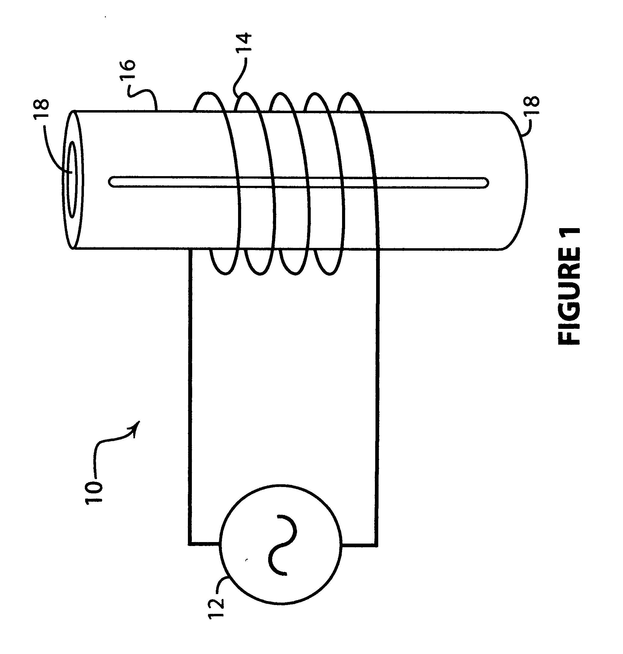
[0023]FIG. 1 illustrates an inductively coupled plasma source 10 in accordance with one embodiment of the invention. An RF power source 12 furnishes alternating current to induction coils 14 disposed coaxially about a substantially metallic plasma discharge tube 16 containing a plasma within. As illustrated in the embodiment of FIG. 1, plasma discharge tube 16 is configured as a hollow cylinder open at both ends 18 to allow for gas inlet and exhaust, as for example in an inline gas processing application. Alternatively, the plasma tube may be configured as a sealed vacuum chamber having metered inlet and exhaust ports for feed and processing gases. Although not shown, the apparatus may also comprise impedance matching elements or circuitry disposed between RF power source 12 and induction coils 14, as well as measurement and feedback circuitry to regulate operation of the device. Also not shown are other features that may typically be included in a plasma processing system such as v...


PUM

PropertyMeasurementUnit
Dielectric polarization enthalpyaaaaaaaaaa
Electrical conductoraaaaaaaaaa
Frequencyaaaaaaaaaa

Abstract

Methods and apparatus are provided for generating an inductively coupled plasma using induced eddy currents. An inductively coupled plasma source of the invention generally comprises a body constructed substantially of a conductive material interrupted by at least one dielectric gap. Radio frequency power is coupled from a current carrier into the conductive body. The one or more dielectric interruptions in the conductive body are disposed so as to cause eddy currents to circulate about portions of the body and thereby couple RF power into a plasma in proximity to the conductive body. By utilizing induced eddy currents to couple power into a plasma, the invention allows for substantial bodies of conductive materials, such as structural metals, to be interposed between the induction coils that receive power from a power generator and the plasma.

Description

BACKGROUND OF THE INVENTION [0001] 1. Field of the Invention [0002] This invention relates generally to plasma processing sources, and more particularly to apparatus and methods for inductively coupled plasma processing. [0003] 2. Brief Description of the Prior Art [0004] Inductively coupled plasma sources in a variety of configurations are employed in a broad range of industrial applications. Inductively coupled plasma processing chambers are used abundantly for modifying the surface properties of materials, as for example in the manufacture of modern integrated circuits. Inductively coupled plasma sources may also operate as remote sources of activated gas species for downstream processing operations, or as abatement devices for treatment of toxic or environmentally harmful materials. [0005] In one form of well known inductively coupled plasma source, radio frequency (RF) power is coupled from inductive coils into a plasma contained within a dielectric enclosure. For example, the ...

Claims


Application Information

Patent Timeline
IPC IPC(8): B31B1/60C23F1/00
CPCH01J37/321H01J37/32458H05H2001/4667H05H1/46H01J37/32807H05H1/4652
Inventor JEWETT, RUSSELL F. JR.SCHOLL, RICHARD A.
Owner ADVANCED ENERGY IND INC
Why Eureka
Try Eureka