
Transmission system, delivery path controller, load information collecting device, and delivery path controlling method

Inactive Publication Date: 2005-08-25
FUJITSU LTD
View PDF22 Cites 489 Cited by
  • Summary
  • Abstract
  • Description
  • Claims
  • Application Information

AI Technical Summary

Benefits of technology

[0025] The present invention has been developed in view of these problems. An object of the present invention is to provide a transmission system, a delivery path controller, a load information collecting device and a delivery path controlling method, capable of preventing an increase in the load placed on delivery servers and an increase in the loads placed on a plurality of routers in the network and the network as a whole, and obtaining delivery paths appropriate for content delivery, in a transmission system for streaming delivery, for example.

Problems solved by technology

With such an increase in the traffic, loads placed on the networks become heavier, so that loads placed on delivery servers for delivering or supplying contents such as images to users over the networks also increase.
The increase in the loads causes packet transmission delay, packet disposition and the like in the networks, and also causes overloads in delivery servers due to an increase in content delivery request messages for content data (transfer requests, transfer request packets, and transfer request messages, hereinafter referred to as “delivery requests” unless otherwise noted) provided to the delivery servers.
Thereby, such a phenomenon as a deterioration in the quality of service (QoS) has been caused frequently.
Conventionally, the bottleneck in using the Internet was accessing parts between client devices (user terminals) and the Internet.
However, since the access speed has been improved, the bottleneck lies in the inner parts (core) of networks or delivery servers for delivering contents, recently.
However, the CDN 140 (see FIG. 15), for example, is subject to quality deterioration when delivery requests from the client devices 80a-80c concentrate on temporarily popular contents such as movies.
In the CDN 140 for load balancing, when delivery requests concentrate on the cache server 81a whereby a high load is placed thereon, there is caused a problem that the streaming quality of a cache server near the client device 80a deteriorates.
Accordingly, when the load placed on the network increases, the content quality to be delivered may be deteriorated although the loads on the delivery servers 150a, 150b are not high, and there is a problem that this probability cannot be eliminated.

Method used


Image

  • Transmission system, delivery path controller, load information collecting device, and delivery path controlling method
  • Transmission system, delivery path controller, load information collecting device, and delivery path controlling method
  • Transmission system, delivery path controller, load information collecting device, and delivery path controlling method

Examples


first embodiment

(A) Explanation of the Present Invention

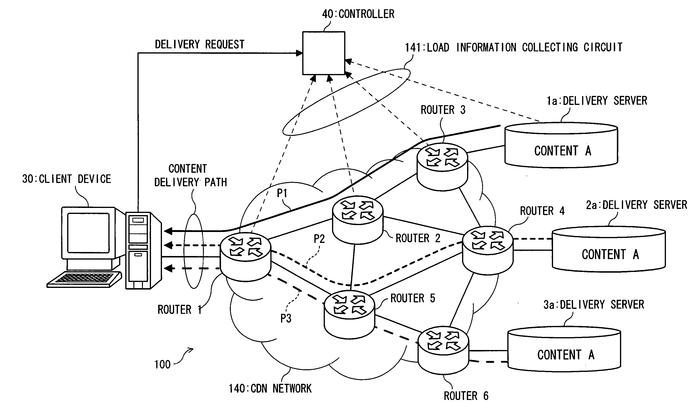
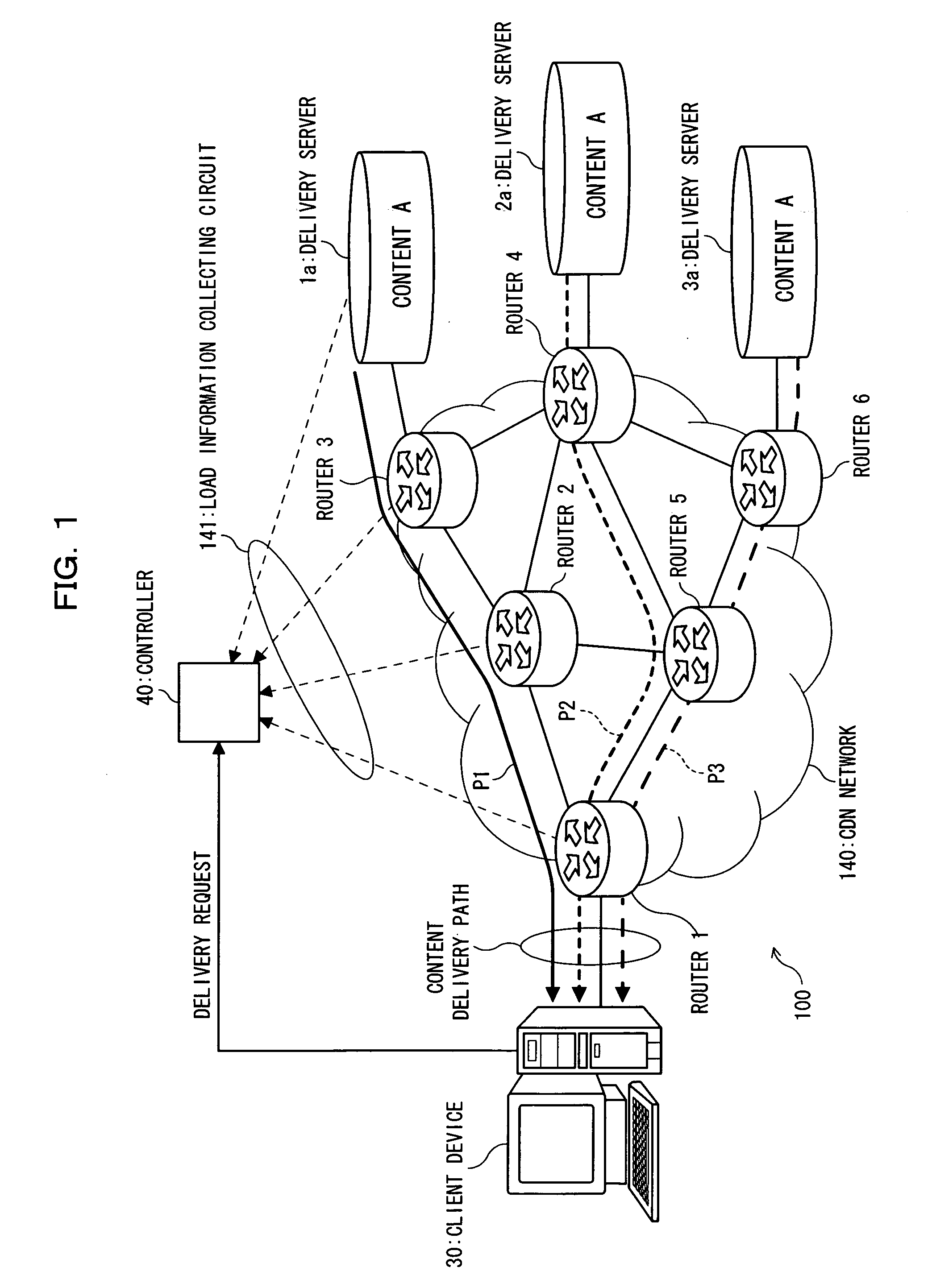
[0063]FIG. 1 is a configuration diagram showing a streaming delivery system (transmission system) according to a first embodiment of the present invention. The streaming delivery system 100 shown in FIG. 1 is for controlling delivery paths while considering costs (load states) of the servers and the links between routers of the network. This system includes: a CDN (Content Delivery Network) 140; six routers 1-6 for example, for transferring packets, provided on the CDN 140; three delivery server side routers 3, 4 and 6 communicating with three delivery servers 1a-3a for example, for delivering contents, among the six routers 1-6; a client side router 1 (router 1) communicating with a client device (client terminal or client) 30 receiving contents, among the six routers 1-6; and a controller (delivery path controller) 40 connected to the routers 1-6, the delivery servers 1a-3a and the client device 30.

[0064] (1) Schematic Configuration of the ...


PUM


Abstract

A transmission system, having a plurality of delivery server side routers which communicate with a plurality of delivery servers for delivering a content; and a client side router which communicates with a client device for receiving the content, is configured to include: a database for storing server load states of the plurality of delivery servers, and respective individual link load states for a plurality of delivery paths between the plurality of delivery server side routers and the client side router; and a path control unit for determining a minimum load state delivery path having a minimum load state among the plurality of delivery paths, based on sums of the server load states and the respective individual link load states stored in the database.

Description

TECHNICAL FIELD [0001] The present invention relates to a transmission system, a delivery path controller, a load information collecting device, and a delivery path controlling method, preferable for content delivery services through which contents such as moving image files are provided to users over, for example, IP (Internet Protocol) networks. BACKGROUND ART [0002] Since the Internet has widely been used by general users (individual, public, companies, government offices, or the like), many users have accessed the Internet over phone lines of slow connections. With the recent development of environment for access to the Internet, various high-speed broadband lines called broadband connections, such as ADSL (Asymmetric Digital Subscriber Line), CATV (Cable Television or Communication Antenna Television), or optical access, are getting available for users. As a result, the volume of packets transferred over networks (traffic or traffic volume) increases dramatically, comparing wit...

Claims


Application Information

Patent Timeline
IPC IPC(8): G06F15/16G06F15/173H04L12/701H04L12/721H04L12/801H04L12/803H04L29/06H04L29/08H04N21/24H04N21/647
CPCH04L45/00H04L45/38H04L47/10H04L47/125H04L69/329H04L67/1008H04L67/101H04L67/1002H04L67/327H04L2029/06054H04L67/10015H04L67/1001H04L67/63
Inventor NAKAMICHI, KOJIYAMADA, AKIKOYAMADA, HITOSHINAGATA, AKIRANAKAMURA, KATSUICHINOMIYAMA, SEIJIFUKAZAWA, MITSUNORIKAWAMURA, NOBUHIROITAGAKI, SUGIKOIAWASAKI, TAKASHI
Owner FUJITSU LTD
Learn More