Liquid ejection head and method of producing the same

a technology of liquid ejection and liquid ejection, which is applied in the direction of printing, etc., can solve the problems of inability to meet the requirements of printing, etc., and achieves the effects of high reliability, low cost and high accuracy

Inactive Publication Date: 2005-08-25
FUJIFILM HLDG CORP +1
View PDF3 Cites 19 Cited by
  • Summary
  • Abstract
  • Description
  • Claims
  • Application Information

AI Technical Summary

Benefits of technology

[0022] The present invention has been made in order to solve the problems of the conventional techniques described above and has an object to provide a liquid ejection head that is capable of forming a high-quality recorded image at high speed by causing ink droplets to be ejected / fly with stability through low-voltage driving and a liquid ejection head production method which makes it possible to produce the liquid ejection head with high accuracy while achieving high productivity.
[0050] With the liquid ejection heads according to the first to third aspects of the present invention, in particular, with the construction according to the second aspect, in which the metal-made ink guide provided on the electrical insulating head substrate and having a sharply pointed tip end is combined with the control electrode, and with the construction according to the third aspect where the ejection electrode is provided on the head substrate and a solution guide having a sharply pointed tip end is provided on the ejection electrode, an electric field can concentrate at the tip end portion of the solution guide. Therefore, it is possible to reduce a pulse voltage necessary for ejection and use an inexpensive IC (control circuit) having a low withstand voltage. As a result, it becomes possible to miniaturize / stabilize the liquid ejection head.
[0051] Also, according to the first to third aspects of the present invention, it becomes possible to supply the charged particles up to the vicinity of the tip end portion of the solution guide and perform high-speed drawing. In addition, electric field interferences do not occur between electrodes, and the sizes of ejected ink droplets are stabilized.
[0052] Further, according to the first to third aspects of the present invention, a distance between the tip end portion of each solution guide and its corresponding control electrode can be set constant, thereby uniformizing an electric field formed by the tip end portion of the solution guide of each ejection portion and stabilizing the ejection.
[0054] Also, with the liquid ejection head production methods according to the second to fourth aspects of the present invention, a liquid ejection head including an ink guide having high reliability and high accuracy can be produced at a low cost.

Problems solved by technology

In the thermal-type ink jet head, however, the ink is partially heated to 300° C. or higher, and a problem arises in that a material for the ink is limited.
Also, when using the piezoelectric-type ink jet head, there occurs a problem in that its structure is complicated and an increase in cost is inevitable.
Therefore, there is a problem in that ink supply takes a long period of time and ink droplets having a stabilized size and colorant particle concentration cannot be successively ejected at a high ejection frequency.
Therefore, there is a problem in that it is difficult to cause a minute droplet to fly and a high voltage is required to cause droplet flying.
Further, in the case of the ink jet heads disclosed in JP 10-76664 A and JP 11-105293 A, it is difficult to obtain a two-dimensionally arrayed head structure.
There is a problem in that ejection portions cannot be arranged at a high density and it is difficult to record a high-quality image at high speed.
Still further, when the ink jet head disclosed in JP 11-105293 A is a line head where it is required to form nozzles at a high density, interferences between the nozzles occur and it is impossible to control the diameters of ink droplets.
There is also a problem in that it is difficult to record a high-quality image.
Therefore, there is a problem in that electric field interferences occur and it is difficult to control ejection concentrations between channels.

Method used


Image

  • Liquid ejection head and method of producing the same
  • Liquid ejection head and method of producing the same
  • Liquid ejection head and method of producing the same

Examples


first embodiment

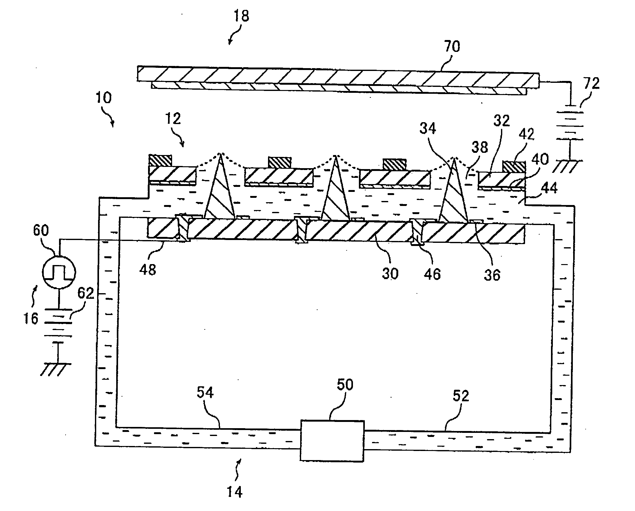
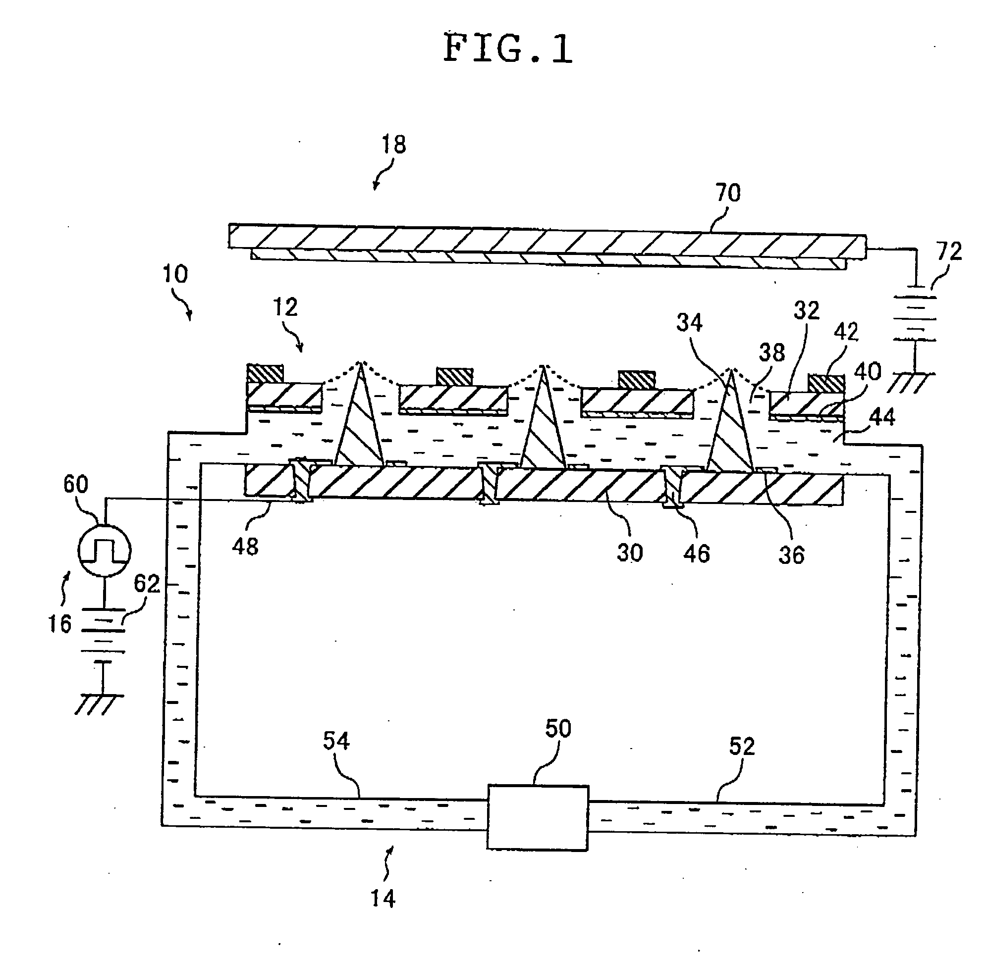
[0153] Next, an ink jet head production method according to an embodiment (first embodiment) of the liquid ejection head production method according to a fourth aspect of the present invention will be described with reference to FIGS. 7A to 7K.

[0154] Here, only one ejection portion is illustrated in FIGS. 7A to 7K, although it is certainly possible to produce two-dimensionally disposed ejection portions at the same time using the production method in this embodiment.

[0155] In this embodiment, a glass substrate 100 is used as an example of a substrate that has an electrical insulation property and serves as a head substrate.

[0156] First, as shown in FIG. 7A, an electrode 102 serving as a wiring portion is formed on the glass substrate 100 by evaporating a metallic film onto the glass substrate 100, producing a mask corresponding to an electrode pattern of the wiring portion on the metallic film using a lithography method for instance, and etching the metallic film using the mask. H...

second embodiment

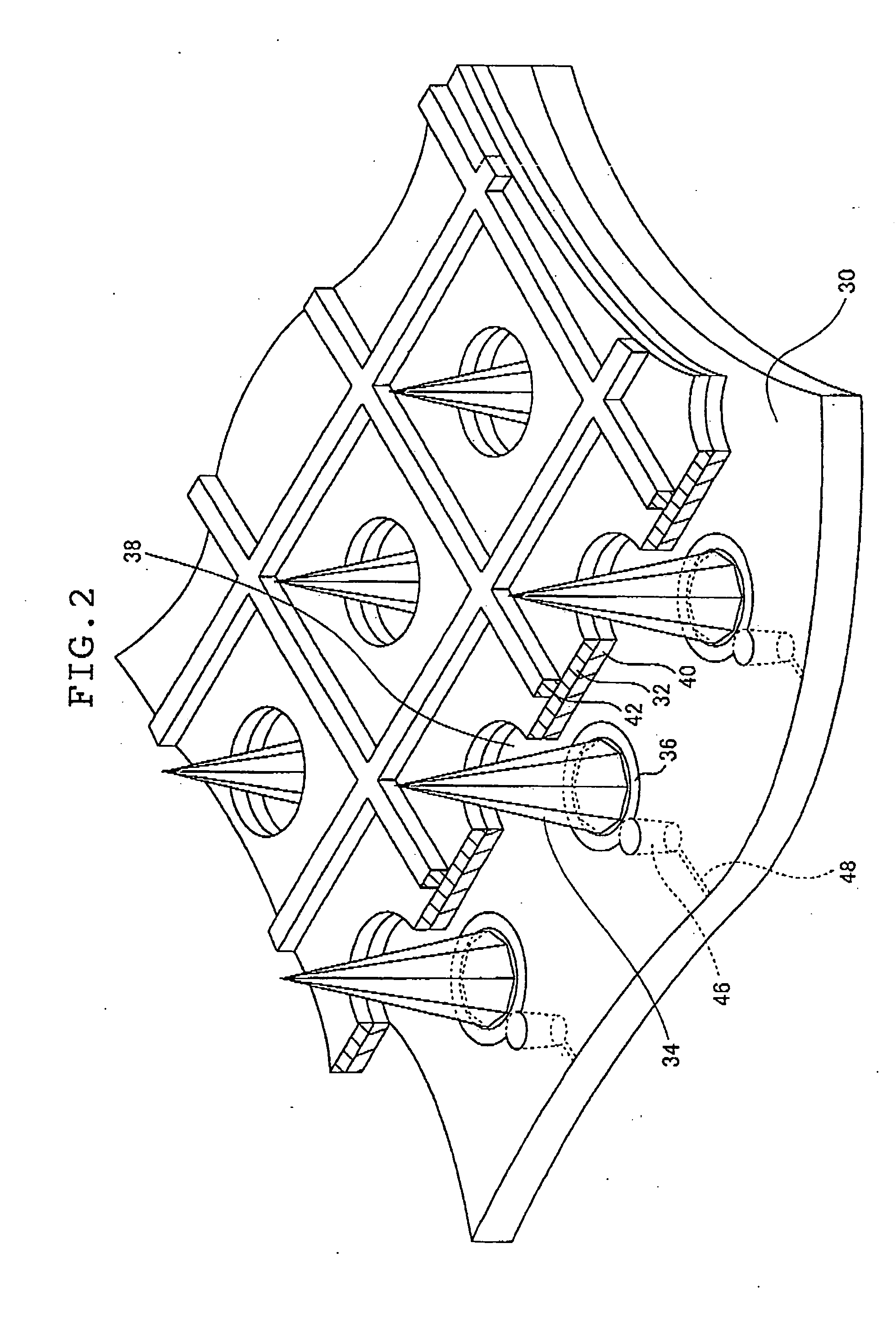
[0175] Next, another embodiment (second embodiment) of the liquid ejection head production method according to the second aspect of the present invention will be described with reference to FIGS. 8A to 8C.

[0176] It should be noted here that the production method in this embodiment is the same as that in the embodiment described above based on FIGS. 7A to 7K except for the ink guide production method. Different points will be mainly described in the following explanation.

[0177] First, like the production method described based on FIGS. 7A to 7K, an electrode 102 serving as a wiring portion is formed for a glass substrate 100, a cylindrical column 104 serving as a convex portion is formed on a surface opposite to the surface on which the electrode 102 has been formed, at a position corresponding to arrangement of an ink guide, an electrode 106 serving as an ejection electrode is formed so as to surround the cylindrical column 104, a through-hole is formed so that the electrode 102 an...


PUM


Abstract

The liquid ejection head ejects droplets by causing an electrostatic force to act on a solution in which charged particles are dispersed. The head includes a solution guide mounted at a position corresponding to a through-hole on a first surface of an insulating head substrate on a through-hole substrate side and gradually narrowing toward a tip end portion, the tip end portion thereof passing through and protruding from the through-hole, a control electrode provided on the first surface of the head substrate so that a center thereof approximately coincides with the solution guide, a electrode drawing portion connected to the control electrode and passing through the head substrate and a wiring portion provided on a second surface being a back side of the head substrate and connecting to each other the electrode drawing portion and means for applying a voltage to the control electrode.

Description

[0001] This application claims priority on Japanese patent applications No. 2004-44416, No. 2004-49344 and No. 2004-51774, the entire contents of which are hereby incorporated by reference. BACKGROUND OF THE INVENTION [0002] The present invention relates to a liquid ejection head that ejects a droplet by causing an electrostatic force to act on a solution in which charged particles are dispersed, and a method of producing the same. [0003] Nowadays, a thermal-type ink jet head that ejects an ink droplet by means of an expansive force of an air bubble generated in ink through heating of the ink and a piezoelectric-type ink jet head that ejects an ink droplet by giving a pressure to ink using a piezoelectric element have been proposed as liquid ejection heads. In the thermal-type ink jet head, however, the ink is partially heated to 300° C. or higher, and a problem arises in that a material for the ink is limited. Also, when using the piezoelectric-type ink jet head, there occurs a pro...

Claims


Application Information

Patent Timeline
Patent Type & Authority Applications(United States)
IPC IPC(8): B41J2/06
CPCB41J2/06
Inventor FUKUNAGA, TOSHIAKIKANEKO, YASUHISA
Owner FUJIFILM HLDG CORP
Why Eureka
Try Eureka