Optical regenerator for high bit rate return-to-zero transmission

a technology of optical regenerators and transmission lines, applied in optics, electrical appliances, instruments, etc., can solve the problems of limiting the transmission distance, reducing the efficiency of the system, and reducing the cost of the system, so as to achieve significant improvement of the system performance and reduce the effect of long distan

Inactive Publication Date: 2005-08-18
ALCATEL LUCENT SAS
View PDF6 Cites 7 Cited by
  • Summary
  • Abstract
  • Description
  • Claims
  • Application Information

AI Technical Summary

Benefits of technology

[0013] This object is achieved in accordance with the invention by using a DI-NOLM comprising an optical loop made of two spools of dispersive fibers with large effective area but of local dispersion of opposite sign as well as a HLN fiber in between. In this configuration according to the invention, the input optical signal needs to be initially chirped either using an additional stage or by placing the apparatus at a given location in the dispersion-managed transmission line. As a consequence of this chirp, incoming pulses are either temporarily compressed or broadened depending of the sign of the local dispersion in the two arms of the optical loop of the DI-NOLM. Then, a nonlinear phase shift is generated between both counterpropagating optical fields inside the HNL as the consequence of the peak power imbalance. Advantageously, it is possible to process RZ or RZ / DSPK with a rather large shape at half-way taking even more than 65% of bit time. This can be achieved without any alteration of the optical regeneration. Moreover, in this configuration by using the method according to the invention, the compensation dispersion is realized inside the DI-NOLM, and so it is not necessary to add a compensating dispersion state at this interferometer.
[0016] Such saturable absorber and optical power limiting functions can be advantageously used to improve RZ-DPSK (but also RZ-On-Off-Keying) transmission system. With RZ-DPSK modulation format and since the data are phase-coded, an interferometer (Mach-Zehnder) is required at the receiver side, as to recover the information in the amplitude domain. Under this condition, the quality of received and amplitude-translated information strongly depends upon the amplitude variations of the RZ-DPSK optical data stream, which can be efficiently reduced when implementing DI-NOLM in the transmission line—hence ensuring also a significantly-improved system performance—.

Problems solved by technology

Optical communications at ultra / high bit rates of return-to-zero (RZ) or RZ / differential phase shift keyed signal (RZ / DSPK) over long distances as for submarine networks suffer from severe degradations occurring during propagation.
This implies that the number of successive repeaters is limited resulting in a limit for the transmission distance.
Furthermore, waveform degradation due to the chromatic dispersion present in optical fibers and the nonlinear optical effects in the fiber are other causes for the transmission limit.
Nevertheless, there are variations in the zero-dispersion wavelength itself along the fiber, the group velocities for the different propagating wavelengths become different from each other, causing a limit to a conversion band and a convertible signal rate.
Thus, such conversion band is limited by dispersion.
Actually, however, the zero-dispersion wavelength varies along the fiber, causing a deviation of the phase matching condition from an ideal condition to result in a limit of the conversion band.
As set up as described in that prior art has the big disadvantage to require a supplementary laser for the input signal light used as pumping light.
Such clock recovery is a real limitation at high rates i.e. at 43 Gbit / s or above.

Method used


Image

  • Optical regenerator for high bit rate return-to-zero transmission
  • Optical regenerator for high bit rate return-to-zero transmission
  • Optical regenerator for high bit rate return-to-zero transmission

Examples


Embodiment Construction

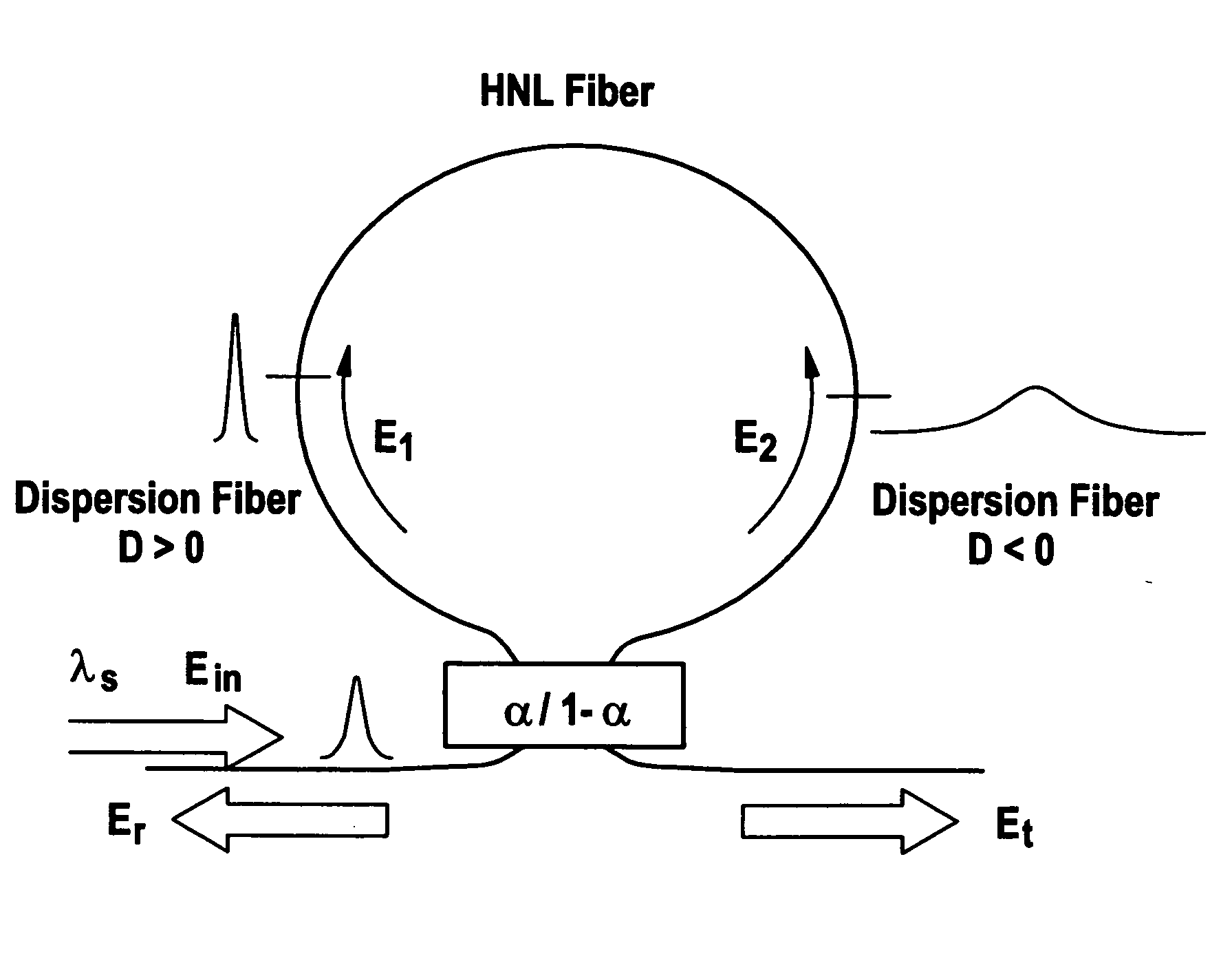
[0023] On FIG. 3 is shown a dispersion imbalanced nonlinear optical loop mirror according to the invention. It comprises a coupler 23 to which are connected an input path 22 and an output path 24 for optical signal. The coupler 23 is chosen such that α=0.5 so that half of the input optical signal will be transmitted on each first and second optical paths connected to that coupler 23 and forming the optical loop path of the DI-NOLM. The optical loop path is made according to the invention of the first 30 and second 32 optical path including a first and a second fibers having different properties as to transmitted optical signals. These first and second fibers show large effective areas with local dispersion of opposite sign. Therefore the optical field E1 launched into the first optical path 30 with i.e. a positive dispersion will be subjected to a sharpening of the pulse. In contrary the other optical field E2 which is launched into the second optical path 32 with negative dispersio...


PUM


Abstract

It is propose to use a DI-NOLM comprising an optical loop made of two spools of dispersive fibers with large effective area but of local dispersion of opposite sign and a HLN fiber in between. In this configuration according to the invention, the input optical signal needs to be initially chirped. A nonlinear phase shift is then generated between both counter propagating optical fields inside the HNL as the consequence of the peak power imbalance. Advantageously, it is possible to process RZ or RZ / DSPK with a rather large shape at half-way taking even more than 65% of bit time. This can be achieved without any alteration of the optical regeneration. Moreover, in this configuration by using the method according to the invention, the compensation dispersion is realized inside the DI-NOLM, and so it is not necessary to add a compensating dispersion state at this interferometer.

Description

TECHNICAL FIELD [0001] The present invention relates to a method and an optical regenerator for waveform shaping of optical signal. The invention is based on a priority application EP 04 290 304.7 which is hereby incorporated by reference. BACKGROUND OF THE INVENTION [0002] Optical communications at ultra / high bit rates of return-to-zero (RZ) or RZ / differential phase shift keyed signal (RZ / DSPK) over long distances as for submarine networks suffer from severe degradations occurring during propagation. Such degradations can be so important to become one of the main limitation at bit rates equal or greater than 40 Gbit / s. Indeed, in an optical fiber communication system that has been put to practical use in recent years, a reduction in signal power due to transmission linear loss, coupling loss, etc. is compensated by using an optical amplifier such as an Erbium-doped fiber amplifier (EDFA). Such optical amplifier is an analog amplifier, which functions to linearly amplify a signal. I...

Claims


Application Information

Patent Timeline
IPC IPC(8): H04B10/2525H04B10/299
CPCH04B10/299H04B10/25253
Inventor SEGUINEAU, FREDERICLECLERC, OLIVIER
Owner ALCATEL LUCENT SAS
Why Eureka
Try Eureka