
Electromagnetic-shielding transparent window member and method for producing the same

Active Publication Date: 2005-08-18
BRIDGESTONE CORP
View PDF9 Cites 12 Cited by
  • Summary
  • Abstract
  • Description
  • Claims
  • Application Information

AI Technical Summary

Benefits of technology

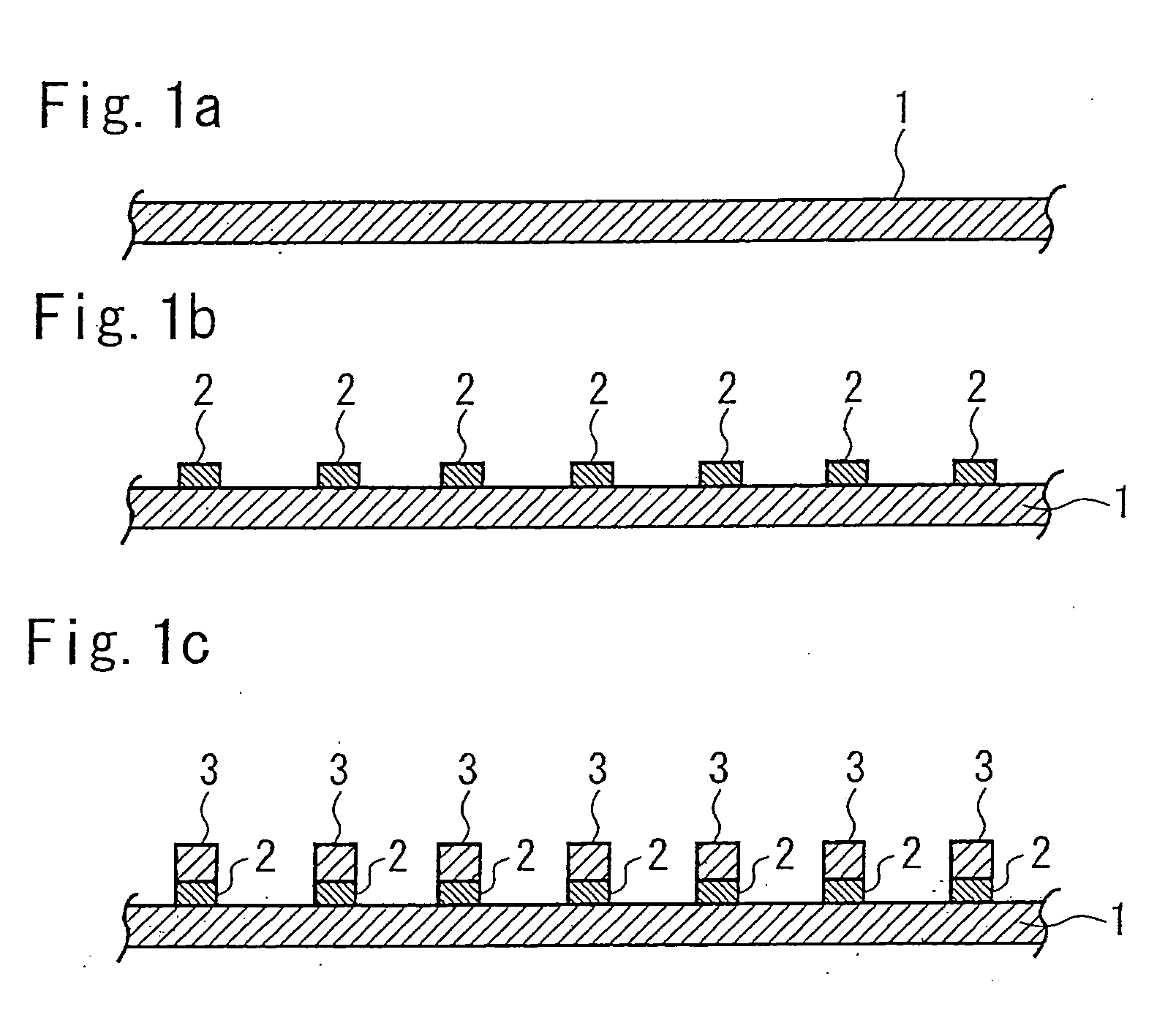
[0013] An object of the present invention is to provide an electromagnetic-shielding transparent window member including a patterned conductor formed by electroless plating and a production method requiring fewer steps for forming the patterned conductor to produce the electromagnetic-shielding transparent window member readily and efficiently at low cost.
[0016] According to the electromagnetic-shielding transparent window member and the method for producing the window member, a fine, precise pattern can be formed with the resin coating material, and a patterned conductor having a significantly small line width and high aperture ratio can be formed on the patterned resin by electroless plating.
[0018] In the present invention, the patterned resin is formed with the catalyst-containing resin coating material, and a conductive material is deposited only on the patterned resin by electroless plating. This method therefore does not involve, for example, etching with an environmentally unfriendly etchant, such as chromium trioxide, and neutralization with a neutralizing liquid such as hydrochloric acid. Thus the patterned conductor can easily be formed at low cost. In addition, the patterned resin does not peel off the transparent film with acid, alkali, or heat.
[0020] The method according to the present invention can therefore readily produce an electromagnetic-shielding transparent window member including a patterned conductor having, for example, a line width of 200 μm or less and an aperture ratio of 75% or more with fewer steps at low cost.

Problems solved by technology

In recent years, the widespread use of office automation (OA) equipment and communications equipment has developed the problem of electromagnetic waves generated from such equipment.
For example, the electromagnetic waves may affect the human body and cause precision equipment to malfunction.
A coarse mesh can be produced with thick fibers, but is extremely difficult to produce with thin fibers.
The window members therefore cannot provide high light transmittance.
In addition, conventional conductive meshes readily cause a moiré pattern (interference fringes) in connection with pixel pitches of light-emitting panels equipped with the electromagnetic-shielding transparent window members.
Such design changes complicate the assembly and incorporation of electromagnetic-shielding transparent window members into casings.

Method used


Image

  • Electromagnetic-shielding transparent window member and method for producing the same
  • Electromagnetic-shielding transparent window member and method for producing the same

Examples


example 1

[0040] A catalyst-containing resin coating material (“Melcoat NMY Type III,” manufactured by Meltex Inc.) was applied to a polyester film having a thickness of 100 μm in a grid pattern by printing. This coating material is prepared by adding 10% by weight of a catalyst for electroless plating, namely palladium chloride, to urethane resin. The resultant patterned resin had a regular square grid pattern including lines 20 μm wide and squares with sides 250 μm long. This patterned resin had an aperture ratio of 80% and a print thickness of about 2 μm after drying.

[0041] After the grid-patterned resin was degreased with 5% sulfuric acid, a copper film having an average thickness of 2 μm was deposited on the resin by electroless plating with a copper electroless plating solution (60° C.) having the following composition:

[Composition of Copper Electroless Plating Solution (Alkaline)]

[0042] Copper sulfate: pentahydrate: 13 g / l [0043] NaOH: 7.5 g / l [0044] HCOH: 13 ml / l

Finally, the patt...


PUM

PropertyMeasurementUnit
Percent by massaaaaaaaaaa
Fractionaaaaaaaaaa
Fractionaaaaaaaaaa

Abstract

A method for producing an electromagnetic-shielding transparent window member including a transparent film and a patterned conductor disposed thereon includes the steps of applying a resin coating material containing a catalyst for electroless plating to the transparent film to form a patterned resin having the same pattern as the patterned conductor to be formed; and depositing a conductive material only on the patterned resin by electroless plating to form the patterned conductor.

Description

CROSS REFERENCE TO RELATED APPLICATION [0001] This is a continuation application of PCT / JP03 / 13156 filed on Oct. 15, 2003.BACKGROUND OF THE INVENTION [0002] 1. Field of the Invention [0003] The present invention relates to electromagnetic-shielding transparent window members useful as, for example, front filters for plasma display panels (PDPs) or window materials (for example, patch films) used in buildings requiring electromagnetic shielding, such as hospitals, and also relates to methods for producing the window members. In particular, the present invention relates to an electromagnetic-shielding transparent window member including a film and a patterned conductor formed thereon, and a method for producing the window member. [0004] 2. Description of the Related Art [0005] In recent years, the widespread use of office automation (OA) equipment and communications equipment has developed the problem of electromagnetic waves generated from such equipment. For example, the electromagn...

Claims


Application Information

Patent Timeline
IPC IPC(8): C23C18/16C23C18/18G02F1/136H05K3/18H05K9/00
CPCH05K3/182H05K9/0096H05K2201/0108H05K2203/0709C23C18/206C23C18/30G02F1/136C23C18/2066C23C18/405C23C18/1608
Inventor KOTSUBO, HIDEFUMI
Owner BRIDGESTONE CORP
Learn More