
Plate package, method of manufacturing a plate package, use of a plate package and plate heat exchanger comprising a plate package

Inactive Publication Date: 2005-08-18
ALFA LAVAL CORP AB
View PDF8 Cites 25 Cited by
  • Summary
  • Abstract
  • Description
  • Claims
  • Application Information

AI Technical Summary

Benefits of technology

[0006] The object of the present invention is to provide a plate package for a plate heat exchanger with an increased fatigue strength.
[0008] By such a prepressing the stresses in both the plates and the joints will increase, and it is possible to exceed the yield limit of the material in certain points or areas. In these points or areas a plastic deformation thus arises, which leads to a decrease of the stress in these points or areas after the pressure again has been lowered to a normal level. During use of the plate package, these points or areas will be subjected to a reduced load, and adjacent points or areas will absorb a larger part of the load that arises. After the prepressing according to the present invention, it is thus possible to obtain favourable rest stresses in the form of pressure stresses in the most loaded area of the plate package. The plate package may for instance include the materials copper and stainless steel, which have a high ductility, and if these materials are used in the plate package the desired condition with an equalised inner stress in the plate package is thus obtained prior to failure of the plate package in the most loaded point or points.
[0010] By the proposed prepressing, it is possible to prolong the life of the plate package at pressure cycling to a low cost. For certain products, which already today have a sufficient life, it is instead, thanks to the invention, possible to dispense with a frequently used pressure plate against which the plate package is arranged.
[0013] According to a further embodiment of the invention, said deformation is achieved by pressurising a supplied medium to a treatment pressure which significantly exceeds the working pressure. By such a pressurising, the plastic deformation may be achieved in a simple and controllable manner.
[0017] The object is also achieved by the initially defined method, which is characterised by the steps of: attaching the plates to each other in a number of joints in such a manner that a permanent joining of the plate package is achieved, and providing at least one local inner plastic deformation of the plate package in such a manner that the plate package obtains an increased strength.

Problems solved by technology

In addition, in such plate packages, a certain spread in the pressure fatigue quality arises since the permanent connection between adjacent plates in certain joints could be defect or possible be partly missing.
These high pressure pulses lead to high stresses in such defect joints and in joints around defect joints or around areas where the joints are partly missing for any reason.

Method used


Image

  • Plate package, method of manufacturing a plate package, use of a plate package and plate heat exchanger comprising a plate package
  • Plate package, method of manufacturing a plate package, use of a plate package and plate heat exchanger comprising a plate package
  • Plate package, method of manufacturing a plate package, use of a plate package and plate heat exchanger comprising a plate package

Examples


Embodiment Construction

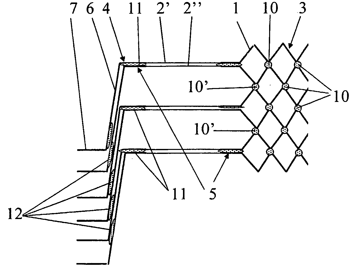
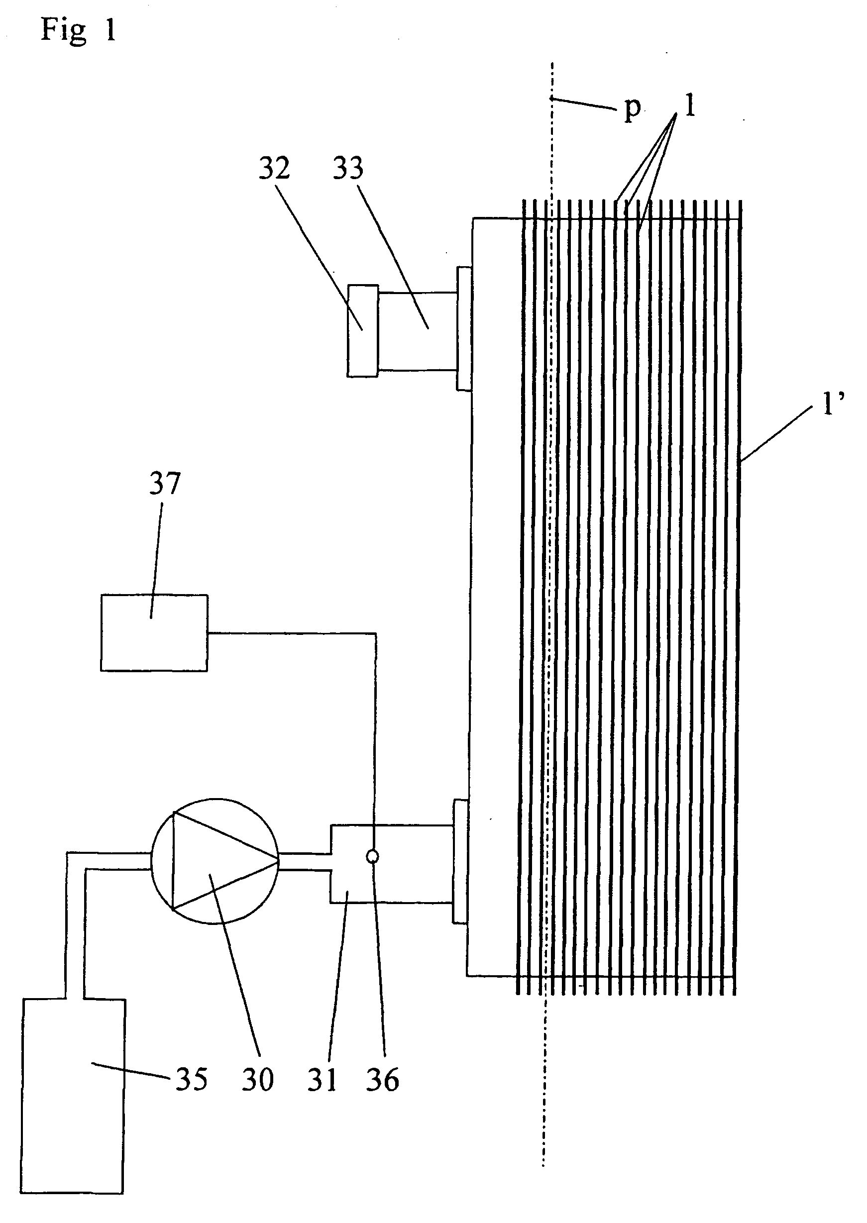
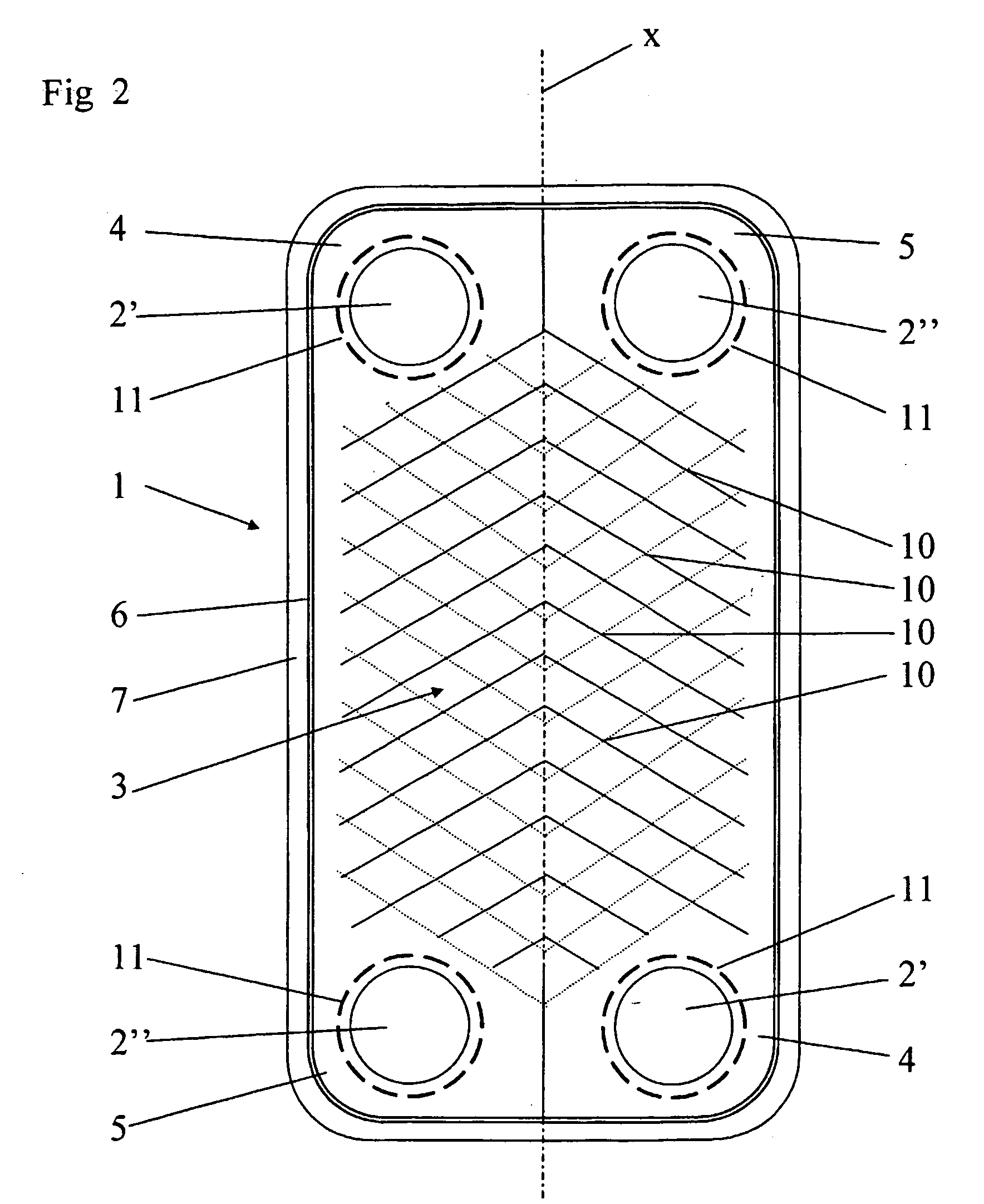
[0026]FIG. 1 discloses a plate heat exchanger including a plate package, which includes a plurality of heat exchanger plates 1. Such a plate 1 is disclosed more closely in FIG. 2. The plate 1 is manufactured of a ductile material, preferably stainless steel. In the embodiment disclosed, each plate 1 includes four portholes 2′, 2″. Each plate 1 includes a main extension plane p and a corrugation 3 of ridges and valleys. The corrugation 3 has been achieved by compression moulding the plates 1. In the embodiment disclosed, the ridges and valleys extend according to a herring-bone pattern, i. e. they are inclined by a determined angle to a longitudinal centre axis x of the plate 1.

[0027] Substantially all plates 1 in the plate package are identical and the portholes 2′, 2″ form four port channels extending through the plate package. The plates 1 are however stacked on each other in such a way that the corrugation 3 of every second plate points in a first direction and every other plate...


PUM

PropertyMeasurementUnit
Forceaaaaaaaaaa
Pressureaaaaaaaaaa
Deformation enthalpyaaaaaaaaaa

Abstract

The invention refers to a plate package for a plate heat exchanger, a method for manufacturing a plate package, a use of a plate package, and a plate heat exchanger. The plate package includes a plurality of heat exchanger plates (1), which are stacked on each other and which each includes a number of portholes. The plates (1) are compression molded and permanently connected to each other in a number of joints in such a manner that the plates between each other form a first passage for a first fluid and a second passage for a second fluid. The plate package is designed to permit at least one of the fluids to flow through the respective passages at a predetermined maximum working pressure. The plate package has an increased strength achieved by subjecting at least one of the passages to at least a local inner plastic deformation of the plate package.

Description

BACKGROUND OF THE INVENTION AND PRIOR ART [0001] The present invention refers to a plate package for a plate heat exchanger, which package includes a plurality of heat exchanger plates, which are stacked on each other and which each includes a number of portholes, wherein the plates are compression moulded and permanently connected to each other in a number of joints in such a manner that the plates between each other form a first passage for a first fluid and a second passage for a second fluid, wherein the plate package is designed to permit at least one of said fluids to flow through the respective passages at a predetermined maximum working pressure. The invention also refers to a method for manufacturing a plate package for a plate heat exchanger, which package includes a plurality of heat exchanger plates, which are stacked on each other and which each includes a number of portholes, wherein the plates are compression moulded in such a manner that the plates in the plate packa...

Claims


Application Information

Patent Timeline
IPC IPC(8): F28F3/08B21D53/04F28D9/00F28D9/02
CPCB21D53/04F28D9/005Y10T29/49366Y10S165/906F28F2225/04F28F2255/10
Inventor BLOMGREN, RALFGRONWALL, JANGRONWALL, KRISTINA
Owner ALFA LAVAL CORP AB
Learn More