
Breathing assistance apparatus

a technology of assistance apparatus and air, which is applied in the direction of inhalators, life-saving devices, and other medical devices, can solve the problems of significant risk of patient rebreathing expired air, inability to precisely control the frequency of inhalation, and undesirable rebreathing of expired air, etc., and achieves the effect of great accuracy

Inactive Publication Date: 2005-08-18
FISHER & PAYKEL HEALTHCARE LTD
View PDF13 Cites 118 Cited by
  • Summary
  • Abstract
  • Description
  • Claims
  • Application Information

AI Technical Summary

Benefits of technology

[0007] It is an object of the present invention to provide a breathing assistance apparatus which goes someway to overcoming the above mentioned disadvantages or which will at least provide the public a useful choice.

Problems solved by technology

When using nasal cannula, however, FiO2 cannot be precisely controlled because it is affected by the route of inhalation (nose or mouth), upper airway geometry and breathing pattern.
These masks are rarely used because they are not easily accepted by patients and carry significant risk of the patient rebreathing expired air.
The rebreathing of expired air is undesirable as this air contains high levels of carbon dioxide.
This system allows the delivery of high flows of oxygen enriched air to the patient, but is limited in the flows achievable due to the narrow bore of the cannula resulting in high resistance gas flow and excessive velocity and noise upon exiting the cannula.
Furthermore, the narrowness of the nasal cannula in this system allows easy expiration of gases between the prongs and nares and therefore does not create any positive airway pressure.
The NASALAIRE™ is not designed to deliver humidified gases to the patient, being unheated and without insulation of any type.

Method used


Image

  • Breathing assistance apparatus
  • Breathing assistance apparatus
  • Breathing assistance apparatus

Examples


Embodiment Construction

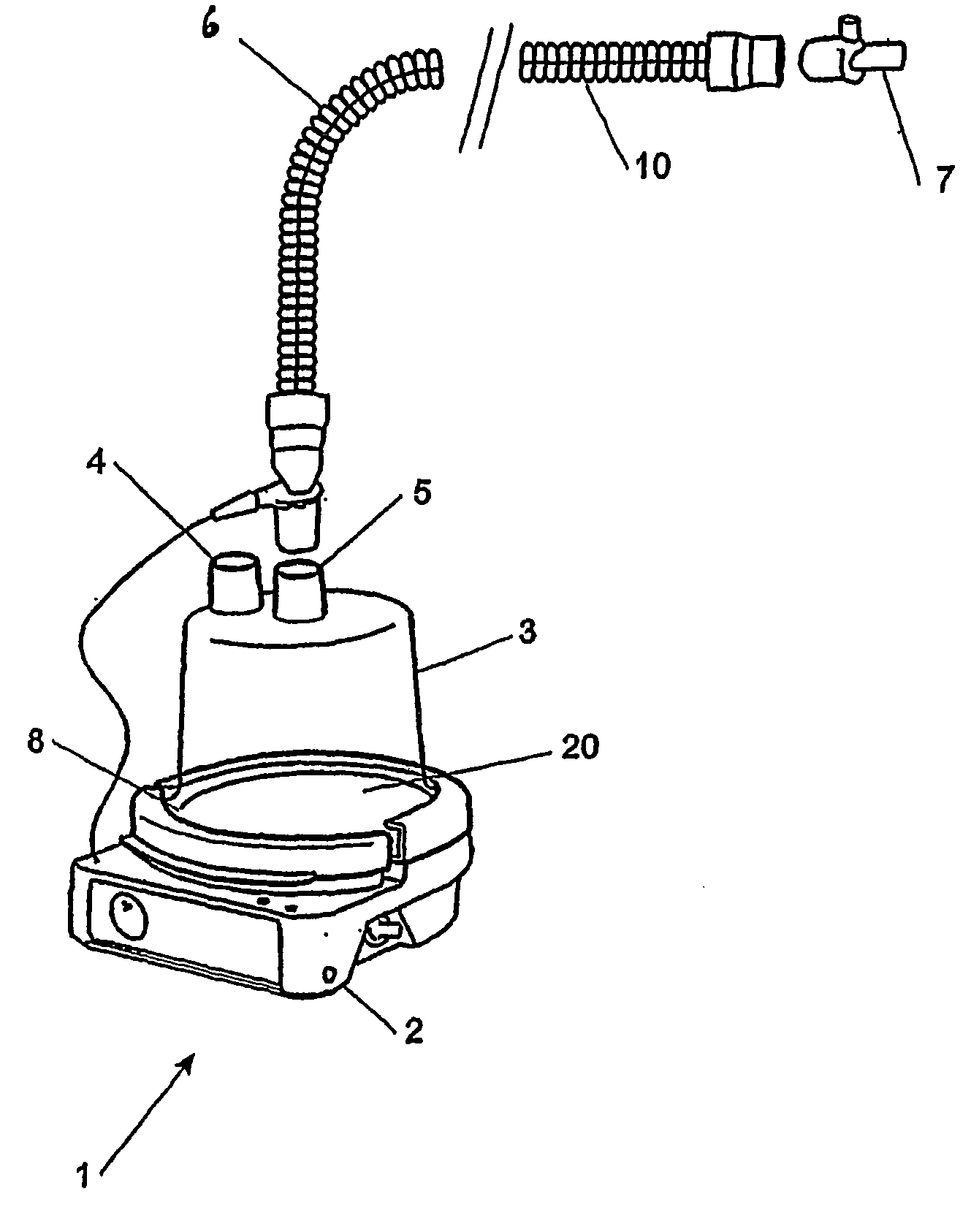
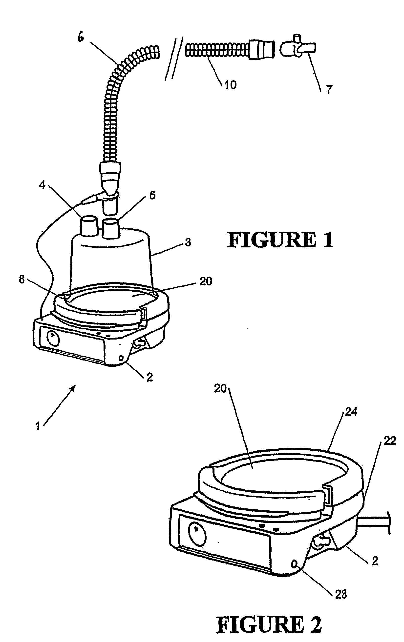
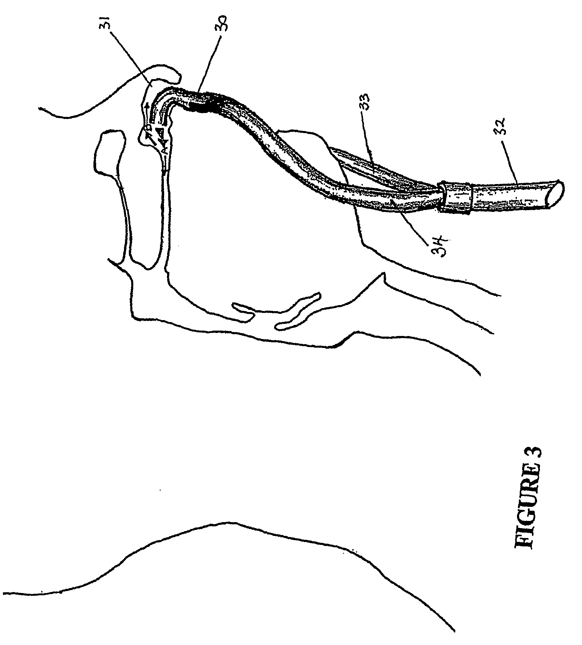
[0025] Whether used in a hospital environment or in a home environment, the nasal cannula of the present invention will generally have associated three main pieces of apparatus. Firstly an active humidifier that controls the temperature of a heater plate heating a body of water to achieve a desired temperature and humidity of the gases being humidified. Secondly a transport conduit from the humidifier to the patient is also required, which is preferably heated to reduce condensation, or “rain out”. Thirdly a cannula designed to fit up into the nasal cavity and deliver humidified, pressurized gases.

[0026] Referring to FIG. 1 a humidifying apparatus as might be used in a hospital generally referenced 1 is shown. The apparatus comprises a body 2 containing heating means comprising a heating plate 20 having an electric heating element therein or in thermal contact therewith and control means for example electronic circuitry which may include a microprocessor for controlling the supply ...


PUM


Abstract

The present invention relates to the delivery of high flow humidified pressurised oxygen and / or air to a patient by way of a wide bore nasal cannula (30). The cannula of the present invention comprises wide bore cannula to minimise the flow resistance and the entry velocity. The nasal cannula includes two nasal prongs (40, 41) fittable into a patient's nostrils. The prongs follow the inner shape of the patient's nostrils such that a more efficient flow of gases into the patient's lungs is achieved as gases flow are directed down the main nasal passage more accurately. The cannula do not seal within the nasal cavities of the patient, and in some embodiments the cannula may be provided with a pressure relief valve to allow gases to be exhausted from the cannula.

Description

FIELD OF INVENTION [0001] The present invention relates particularly, though not solely, to the delivery of high flow humidified pressurised oxygen and / or air by way of a wide bore nasal cannula to a patient in need of respiratory support. SUMMARY OF THE PRIOR ART [0002] There are two common methods for delivering oxygen to a patient. The simplest method is via a Venturi mask This method has the advantage of delivering, precisely and constantly, the desired level of oxygen, or fraction of inspired oxygen (FiO2), provided that the FiO2 is less than 50%. The operation of a Venturi mask is based on the Bernoulli principle. One hundred per cent oxygen flowing through the narrow orifice results in a high-velocity stream that entrains room air through multiple open side ports at the base of the mask or on top a humidifier. The amount of room air entrained to dilute the oxygen depends on the orifice size. Venturi masks can provide FiO2 levels from 24-50% with great accuracy. [0003] The oth...

Claims


Application Information

Patent Timeline
Patent Type & Authority Applications(United States)
IPC IPC(8): A61M16/06
CPCA61M16/0666A61M16/0683A61M16/16A61M16/208A61M16/209A61M16/1085A61M16/109A61M16/1095A61M2206/10A61M16/0006A61M16/0672
Inventor MACKIE, SCOTT ROBERTWHITE, CRAIG KARLFOREMAN, MARK
Owner FISHER & PAYKEL HEALTHCARE LTD
Learn More