
Randomly changing pulse polarity and phase in an UWB signal for power spectrum density shaping

a technology of power spectrum density and random change, applied in the field of wireless communication, can solve the problems of power reduction, decrease and achieve the effect of reducing the performance and range of the signal

Inactive Publication Date: 2005-08-11
MITSUBISHI ELECTRIC RES LAB INC
View PDF10 Cites 23 Cited by
  • Summary
  • Abstract
  • Description
  • Claims
  • Application Information

AI Technical Summary

Benefits of technology

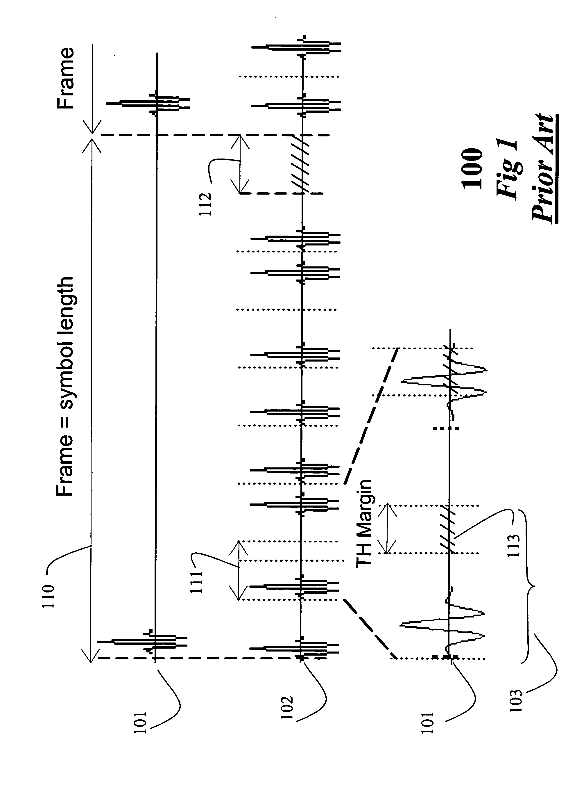
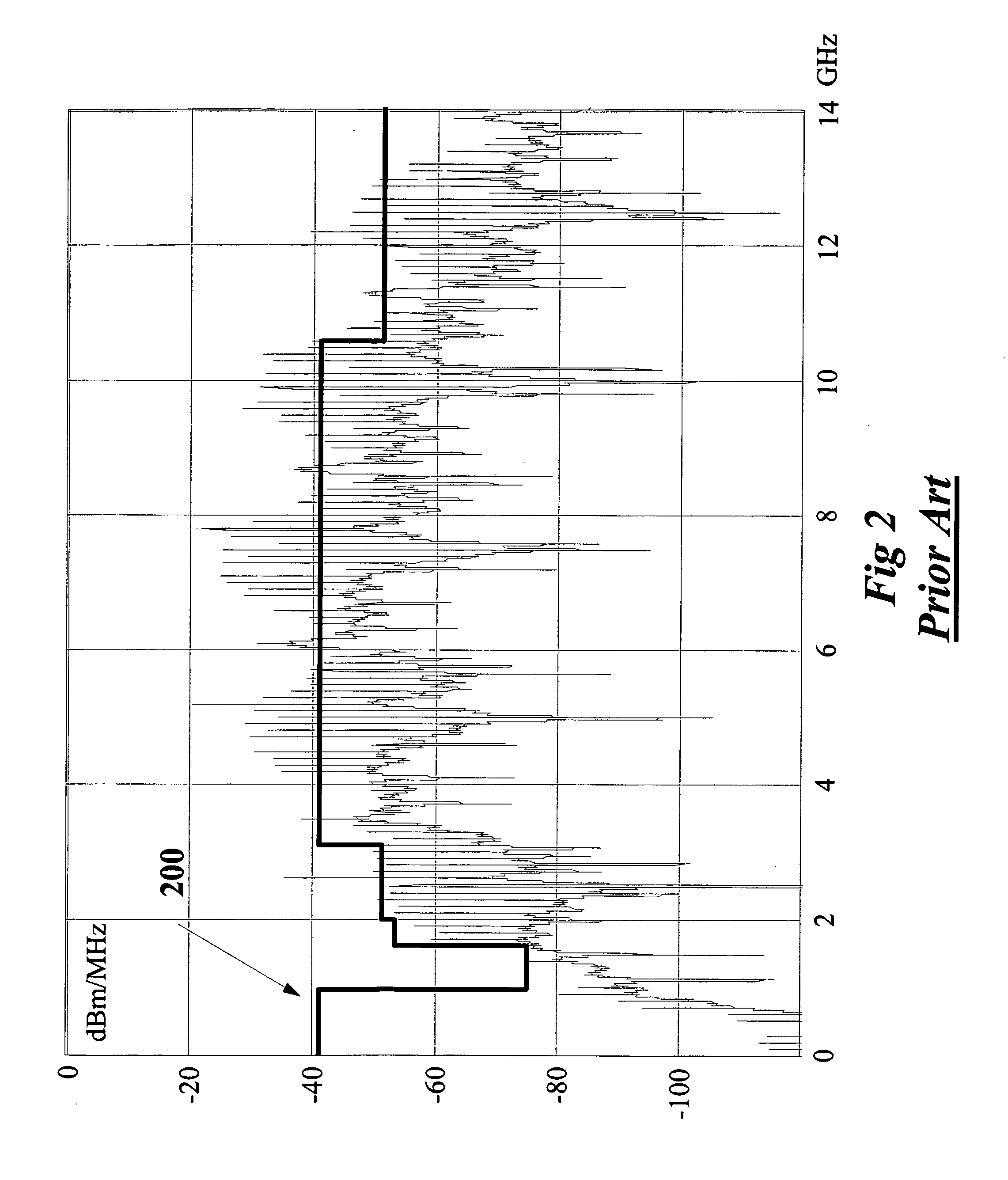
[0018] Commonly, ultra wide bandwidth (UWB) systems communicate with trains of short-duration pulses that have a low duty-cycle. Thus, the energy of the radio signal is spread very thinly over a wide range of frequencies. Almost all of the known systems use a combination of spreading techniques such as time-hopping (TH) spreading for multiple access, and modulation formats such as pulse position modulation (PPM). This combination results in spectral lines that either lead to a violation of FCC requirements, or require a significant reduction in power, which decreases performance and range of the signal.
[0019] The invention provides a method for eliminating spectral lines caused by transmitting data using modulation formats and spreading techniques such as PPM and TH sequences. The spectral lines are eliminated by randomly changing the polarity of the pulses of the signal. Hereinafter, the word ‘random’ means pseudo-random as commonly used in the art.
[0020] Similarly, spectral lines can be eliminated in bandpass signals by randomizing the phase of the pulses in a signal. It is understood for this invention that all methods and apparatuses that are proposed for polarity randomization have their equivalents for phase randomization.
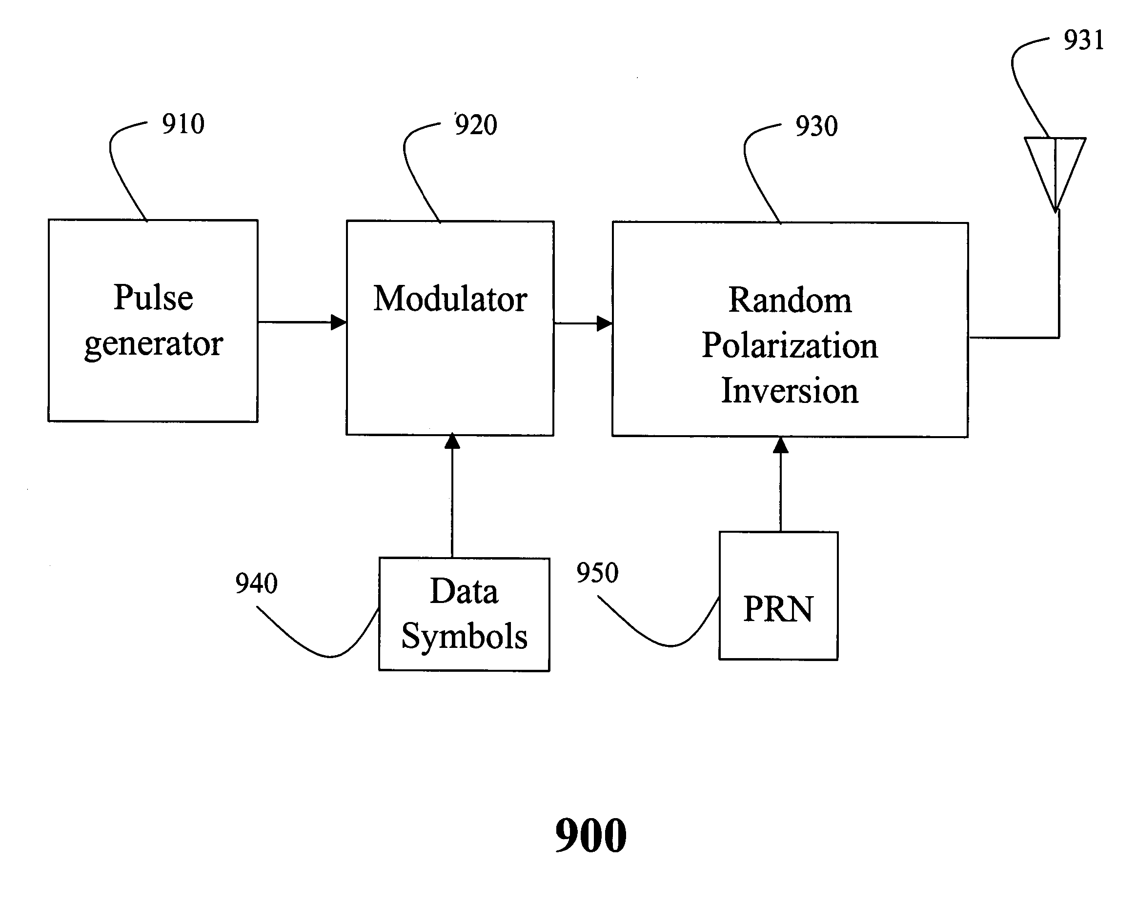
[0022] A method eliminates spectral lines in an ultra wide bandwidth signal. First, a train of pulses is generated. The pulses are then modulated in time according to symbols. A polarity of the pulses is inverted randomly before transmitting the pulses as an ultra wide bandwidth signal.

Problems solved by technology

This combination results in spectral lines that either lead to a violation of FCC requirements, or require a significant reduction in power, which decreases performance and range of the signal.

Method used


Image

  • Randomly changing pulse polarity and phase in an UWB signal for power spectrum density shaping
  • Randomly changing pulse polarity and phase in an UWB signal for power spectrum density shaping
  • Randomly changing pulse polarity and phase in an UWB signal for power spectrum density shaping

Examples


Embodiment Construction

[0051] To solve the problem of discrete frequency components in a spectrum of an ultra wide bandwidth (UWB) radio signal, the invention inverts randomly the polarity of the signal. The resultant signal with randomly inverted polarity is compliant with FCC regulations. It should be noted that the polarity randomization can be applied to pulses, to subparts of symbols, to an entire symbol, and to groups of symbols. Subparts of a symbol can be chips of spreading sequences and elements of codewords of a modulation scheme. This random polarization enables the invention to eliminate spectral lines and to shape the power spectral density of the signal.

[0052] To solve the problem of shaping a spectrum of an ultra wide bandwidth (UWB) radio signal, the invention inverts randomly the polarity of the signal. The resultant signal with randomly inverted polarity can more closely approximate a prescribed spectral mask, the FCC power spectral density (PSD) mask 200 of FIG. 2, than a signal withou...


PUM


Abstract

A method eliminates spectral lines and shapes the power spectral density of an ultra bandwidth signal. First, a train of pulses is generated. The pulses are then modulated in time according to symbols. A polarity of the pulses is inverted randomly before transmitting the pulses as an ultra wide bandwidth signal.

Description

RELATED APPLICATION [0001] This Application is a Continuation-in-Part of U.S. patent application Ser. No. 10 / 361,315 titled “Randomly Inverting Pulse Polarity in an UWB Signal for Power Spectrum Density Shaping” filed on Feb. 10, 2003 by Nakache et al.FIELD OF THE INVENTION [0002] This invention relates generally to wireless communication, and more particularly to communicating with ultra wide bandwidth (UWB) systems. BACKGROUND OF THE INVENTION [0003] Ultra wide bandwidth (UWB) systems have recently received considerable attention for wireless radio communication systems. Recently, the US Federal Communications Commission (FCC) has allowed UWB systems for limited indoor and outdoor applications. [0004] The IEEE 802.15.3a standards group has defined performance requirements for the use of UWB in short-range indoor communication systems. Throughput of at least 110 Mbps at 10 meters are required. This means that the transmission data rate must be greater. Furthermore, a bit rate of at...

Claims


Application Information

Patent Timeline
IPC IPC(8): G01S13/02H04B1/69H04L25/03
CPCH04B1/71632H04B1/7176H04L25/03866H04B2001/6908H04B1/719
Inventor NAKACHE, YVES-PAULMOLISCH, ANDREAS F.ZHANG, JINYUN
Owner MITSUBISHI ELECTRIC RES LAB INC
Learn More