Spark igniter for gas turbine engine

a technology of spark igniter and gas turbine engine, which is applied in the ignition of turbine/propulsion engine, engine starter, lighting and heating apparatus, etc., can solve the problem of insulator inside the igniter erosion

Inactive Publication Date: 2005-08-11
GENERAL ELECTRIC CO
View PDF19 Cites 4 Cited by
  • Summary
  • Abstract
  • Description
  • Claims
  • Application Information

AI Technical Summary

Benefits of technology

[0020] The exposed auxiliary ground electrode can be detected by the fact that, when a spark occurs, a small current travels through the auxiliary ground electrode. When that current is detected, its presence indicates the exposure. Alternately, the exposed auxiliary ground electrode can be visually detected by a human observer, perhaps by using a borescope.

Problems solved by technology

Normal operation of an igniter in a gas turbine engine causes erosion of an insulator inside the igniter.

Method used


Image

  • Spark igniter for gas turbine engine
  • Spark igniter for gas turbine engine
  • Spark igniter for gas turbine engine

Examples


Embodiment Construction

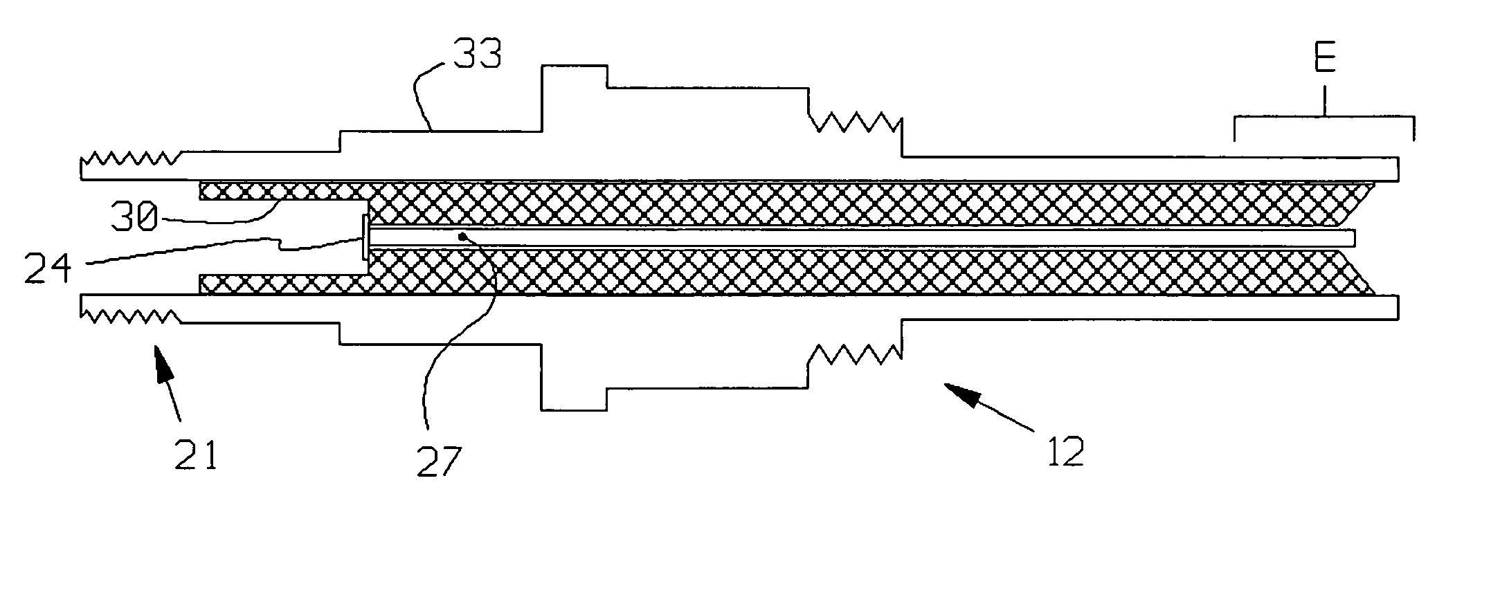
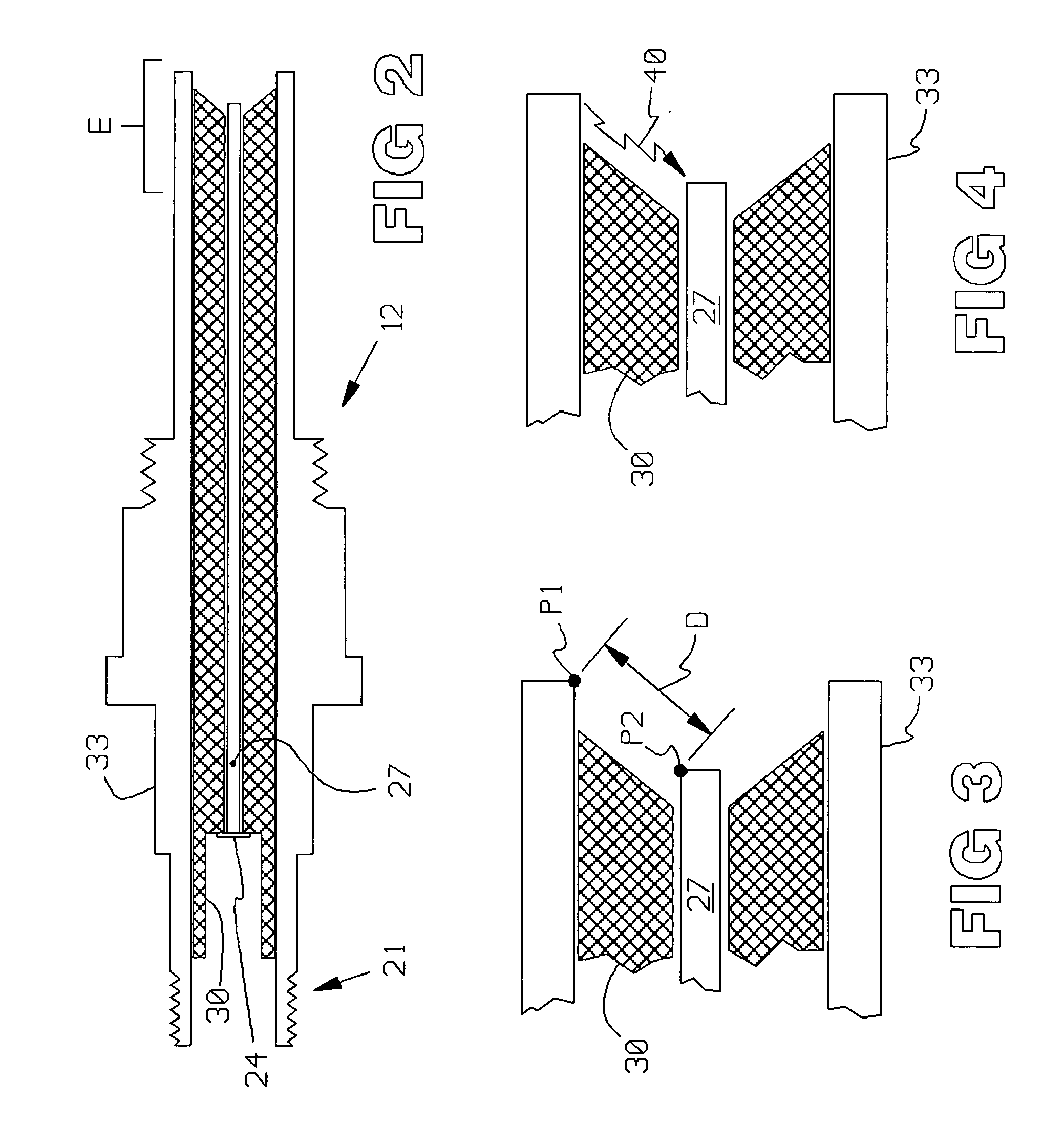
[0035]FIG. 2 illustrates an igniter 12 used in the prior art. An electrical connector (not shown) is threaded onto threads 21, and contains an electrical contact (not shown) which mates with the end 24 of electrode 27. Insulator 30 isolates electrode 27 from the shell 33 of the igniter 12.

[0036] End E of the igniter 12 is shown in FIGS. 3 and 4. A very simplified explanation of the physics involved in plasma generation will be given.

[0037] In operation, a high voltage is applied to the electrode 27, thereby creating a voltage difference, or potential difference, V between points P1 and P2 in FIG. 3. The electric field in that region equals the potential difference V divided by the distance D between the points P1 and P2. For example, if the voltage is 20,000 volts and the distance D is 10 millimeters, or 0.01 meter, then the electric field equals 20,000 / 0.01, or 2 million volts per meter.

[0038] The electric field is designed to exceed the dielectric breakdown strength of the mate...


PUM


Abstract

An igniter for a gas turbine engine. An igniter generates a plasma, or spark, somewhat similar to an automotive spark plug. In the invention, an auxiliary electrode is provided, which is embedded in and covered by a solid insulator. During initial phases of operation, no part of the plasma generated contacts the auxiliary electrode. However, eventually, the covering insulation is eroded by the plasma, and the auxiliary electrode becomes exposed and available as a return path for the plasma. The igniter is constructed so that, when this erosion occurs, the lifetime of the igniter is near its end. Detection of this erosion, as by detecting the new current in the auxiliary ground electrode, indicates the approaching end-of-lifetime.

Description

CROSS REFERENCE TO RELATED APPLICATIONS [0001] This Application is related to subject matter in the following patent applications, which are of common inventorship and filed concurrently herewith: [0002] SENSOR FOR DETECTION OF SPARK IN IGNITER IN GAS TURBINE ENGINE, Ser. No. __ / ___,___; [0003] METHOD OF INFORMING PILOT OF AIRCRAFT OF SPARK DETECTED IN GAS TURBINE ENGINE, Ser. No. __ / ___,___; [0004] PASSIVE, HIGH-TEMPERATURE AMPLIFIER FOR AMPLIFYING SPARK SIGNALS DETECTED IN IGNITER IN GAS TURBINE ENGINE, Ser. No. __ / ___,___; [0005] INTEGRAL SPARK DETECTOR IN FITTING WHICH SUPPORTS IGNITER IN GAS TURBINE ENGINE, Ser. No. __ / ___,___; and [0006] DETECTING SPARK IN IGNITER OF GAS TURBINE ENGINE BY DETECTING SIGNALS IN GROUNDED RF SHIELDING, Ser. No. __ / ___,___.FIELD OF THE INVENTION [0007] The invention relates to gas turbine engines, and igniters therein. BACKGROUND OF THE INVENTION [0008] This Background will explain why the lack of absolute certainty in lifetimes of igniters used in...

Claims


Application Information

Patent Timeline
Patent Type & Authority Applications(United States)
IPC IPC(8): H05H1/24F02C7/00F02C7/26F02C7/266F23Q3/00F23R3/00H01T13/22H01T13/34H01T13/50
CPCF02C7/266H01T13/50F23Q3/006
Inventor PONZIANI, ROBERT L.EARWOOD, ROY
Owner GENERAL ELECTRIC CO
Why Eureka
Try Eureka