
Artificial intervertebral disc

a technology discs, which is applied in the field of artificial intervertebral discs, can solve the problems that the intervertebral disc itself can also be a source of pain

Inactive Publication Date: 2005-07-28
F3 TECH
View PDF99 Cites 166 Cited by
  • Summary
  • Abstract
  • Description
  • Claims
  • Application Information

AI Technical Summary

Benefits of technology

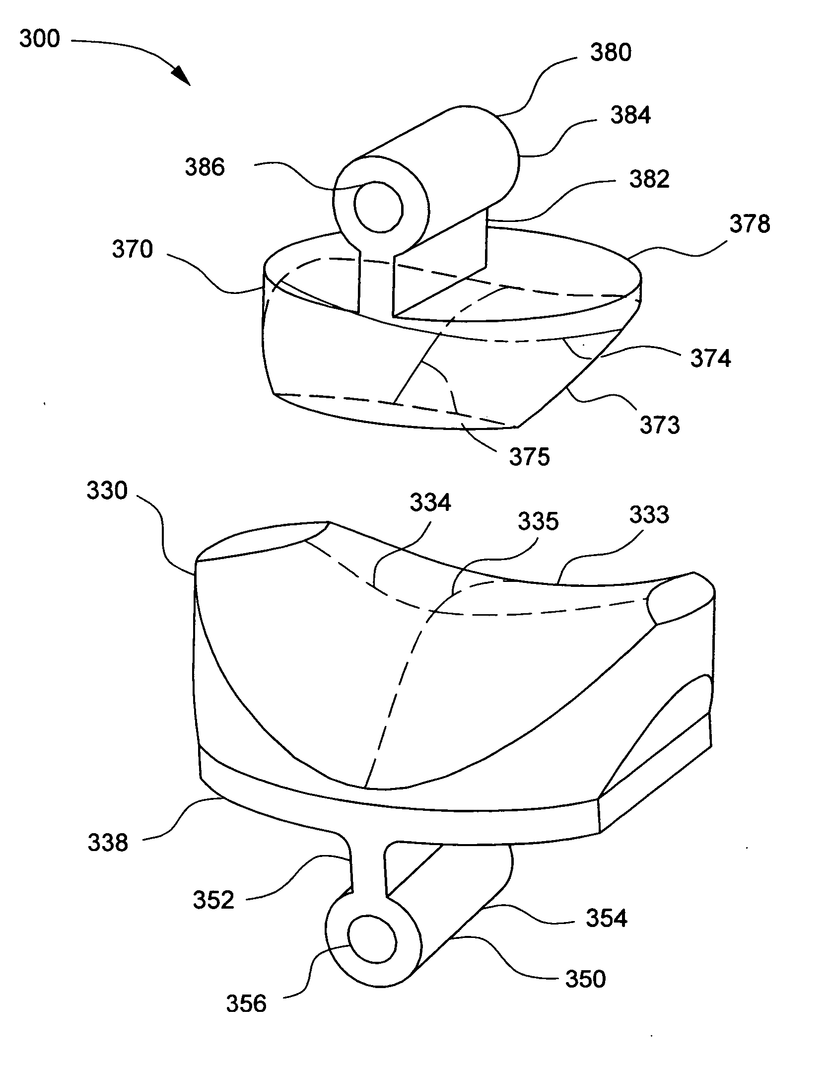
[0009] A first embodiment of the artificial disc of the present invention for the cervical spine includes a disc body having an articulating concave-convex surface secured to a base plate, which may incorporate a bone anchor. A second embodiment of the artificial disc of the present invention is comprised of an articulating concave-convex surface, bone anchor, and a disc body slidably attached to a base plate to permit additional motion. A third embodiment of the artificial disc of the present invention includes an upper disc body and a lower disc body cooperatively forming a saddle-joint. The upper disc body and lower disc body of the third embodiment are securely anchored to vertebral bodies using bone anchors. Further embodiments of the artificial disc of the present invention include an upper disc body and a lower disc body cooperatively forming a saddle-joint, and bone anchors adapted with a tension element to provide additional stability.

Problems solved by technology

The intervertebral disc itself can also be a source of pain.

Method used


Image

  • Artificial intervertebral disc
  • Artificial intervertebral disc
  • Artificial intervertebral disc

Examples


Embodiment Construction

[0023] Consistent with common medical nomenclature, superior is nearer the head in relation to a specific reference point, whereas, inferior is nearer the feet in relation to a specific reference point. Anterior is forward in relation to a specific reference point and posterior is rearward in relation to a specific reference point. The midsagittal plane is an imaginary plane dividing the body into a right side and left side. A frontal plane is any imaginary vertical plane orthogonal to the midsagittal plane.

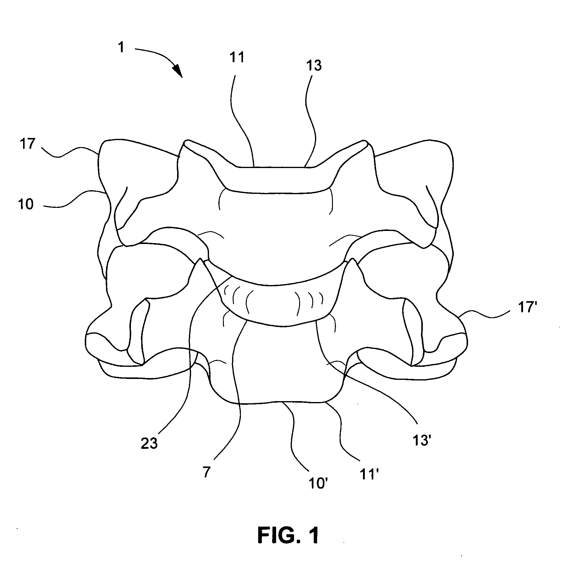
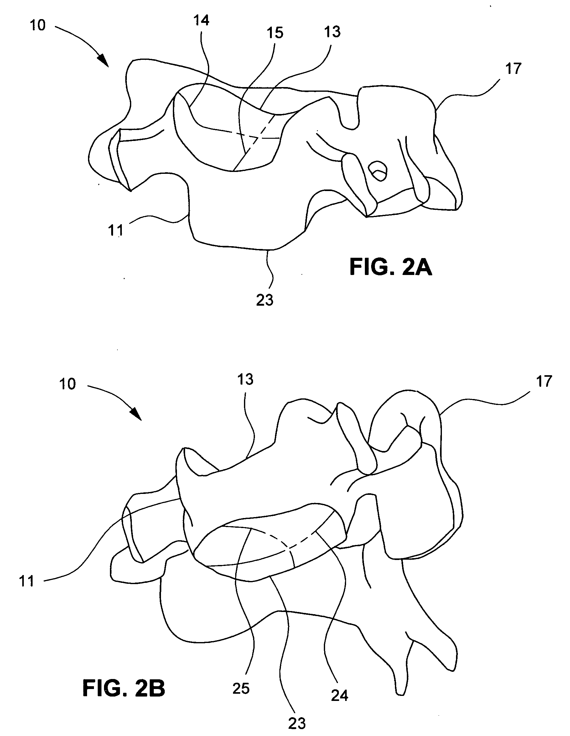
[0024]FIG. 1 shows a cervical spinal motion segment 1 characteristic of the middle and lower cervical spine comprised of a superior vertebra 10, an intervertebral disc 7, and an inferior vertebra 10′. Superior vertebra 10 is divided into two regions to include superior vertebral body 11 and superior posterior elements 17. Similarly, inferior vertebra 10′ is divided into two regions to include inferior vertebral body 11′ and inferior posterior elements 17′. Although separated by ...


PUM


Abstract

An artificial intervertebral disc for at least partially replacing a diseased or damaged intervertebral disc. The artificial disc includes a concave-convex articulating surface. The artificial disc can be used in the cervical region of the spine, where a concave-convex articulating surface is advantageous for improved anatomical fit and region appropriate kinematics. The artificial disc of the present invention also includes an anchor for attachment to bone.

Description

FIELD OF THE INVENTION [0001] The present invention generally relates to an apparatus for the treatment of spinal disorders and, in particular, an artificial intervertebral disc, an implant that replaces a diseased or damaged intervertebral disc. BACKGROUND OF THE INVENTION [0002] There are many painful disorders of the spine, many relating, at least in part, to diseased or damaged intervertebral discs. Disorders include Degenerative Disc Disease, generally an age related disorder where the intervertebral disc gradually loses its water content, resiliency, and height. With a loss in intervertebral disc height and associated loss of normal spacing between vertebrae, motion of the vertebrae can place pressure on the spinal cord or exiting nerve roots. The intervertebral disc itself can also be a source of pain. Spinal disorders, commonly referred to as disc herniation and bulging disc, place painful pressure on the spinal cord and exiting nerve roots. Abnormal bone growth, called oste...

Claims


Application Information

Patent Timeline
IPC IPC(8): A61B17/70A61F2/00A61F2/30A61F2/44
CPCA61B17/7007A61F2310/00029A61F2/4425A61F2002/30301A61F2002/30364A61F2002/30369A61F2002/30462A61F2002/30507A61F2002/30883A61F2002/30884A61F2220/0025A61F2220/0033A61F2220/0075A61F2230/0095A61F2310/00017A61F2310/00023A61B17/701
Inventor MUHANNA, NABIL L.MIDDLETON, LANCE M.
Owner F3 TECH
Learn More