
Self-luminous elements and method for producing the same

a technology of self-luminous elements and luminous elements, which is applied in the direction of vacuum obtaining/maintenance, tubes with screens, discharge tubes luminescnet screens, etc., can solve the problems of high cost of above-mentioned getter rings, affecting the operation life of devices, and requiring labor for mounting getter rings

Inactive Publication Date: 2005-07-28
FUTABA CORPORATION
View PDF8 Cites 10 Cited by
  • Summary
  • Abstract
  • Description
  • Claims
  • Application Information

AI Technical Summary

Benefits of technology

[0019] An object of the present invention is to provide a gas occlusion material, which is safe, easy to handle, saves space, and absorbs residual gases inside a hermetic envelope to maintain the hermetic envelope in high vacuum degree, in place of the conventional metal getter.
[0023] In order to maintain the luminous characteristics of an EL display device, or a self-luminous element, the cleaning degree is maintained so as to exclude internal unnecessary gases after luminous elements are sealed inside the enclosure.
[0024] In order to solve the above-mentioned problems, the present invention uses a relatively safe ZrOx (where 1≦×≦2). According to the present invention, a gas occlusion material containing a zirconium dioxide is disposed in a hermetic envelope so as to be exposed in an atmosphere in the hermetic envelope. Thus, the gas occlusion material absorbs undesired gases inside the hermetic envelope of a self-luminous element, thus improving the reliability of the self-luminous element.
[0039] The present invention can provide a gas occlusion material, which is safer than the conventional metal getter, is easy to handle, saves the space, and absorbs residual gases inside a hermetic envelope to maintain the hermetic envelope in high vacuum degree. The gas occlusion material containing ZrOx (where 1≦×≦2), which is a safe material, can be disposed as various members, constituting a self-luminous element, inside a hermetic envelope. Thus, in an atmosphere of the hermetic envelope, the gas occlusion material can effectively maintain the inside of the hermetic envelope in a clean state.
[0040] In self-luminous elements using electron beam excitation emission, the gas occlusion material can maintain the inside of the vacuum hermetic envelope in high vacuum degree and can clean the inner surface of the envelope and the fluorescent substance surface.
[0042] In order to maintain the luminous characteristics of EL display devices being self-luminous elements, after luminous elements are sealed inside an envelope, the gas occlusion material can effectively maintain the envelope in no existence of internal unnecessary gases.

Problems solved by technology

In plasma display devices being self-luminous elements, unnecessary gases, other than the display gas such as a plasma excitation gas, that form within or enter the envelope after it has been evacuated to a high degree of vacuum, adversely affect the operational life of the device.
Tokkai 2001-76653) However, the problem is that the above-mentioned getter ring is expensive and requires a space for installation in the vacuum envelope and requires labor for mounting a getter ring.
The non-evaporation type getter (NEG), however, is expensive and requires the activation workability.
However, the fixing solution evaporates during the sealing step and is drawn out.
However, this technique has a problem in a practical use because only an auxiliary effect of creating and maintaining a high degree of vacuum degree was confirmed.
The Ba series getters have been practically used as getters generally usable in a temperature range of 140° C. to 120° C. However, a high melting point metal material, such as Ti, Mo, or Zr, has not been used practically as a getter material.
Powders of high melting point metal, being the getter material, may generally be unstable because it can catch fire when in contact with the air.
Moreover, the metal powders do not often have a sufficient gas occlusion capability.
The problem, however, is that any one of those techniques requires a room for disposing a getter material and requires the step of activating the surface of the metal getter material though h-f induction heating or resistance heating after the getter material has been placed in the envelope.

Method used


Image

  • Self-luminous elements and method for producing the same
  • Self-luminous elements and method for producing the same
  • Self-luminous elements and method for producing the same

Examples


embodiment 1

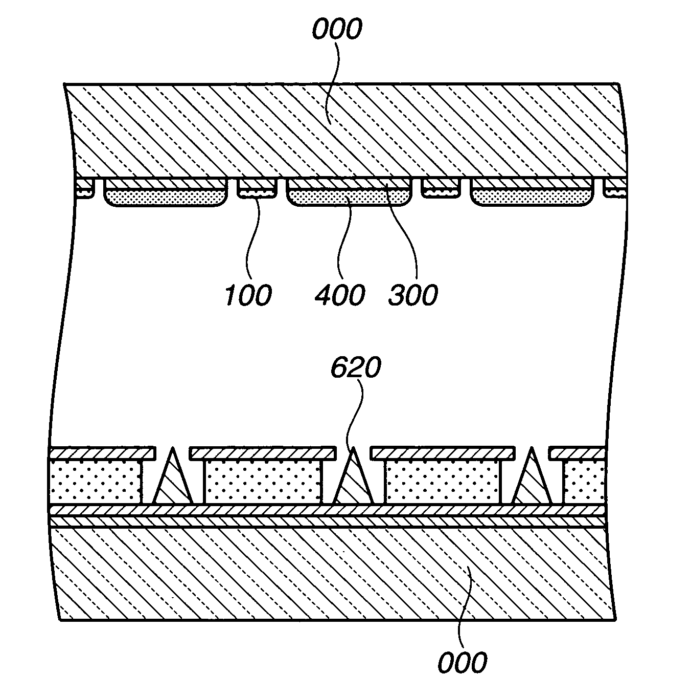
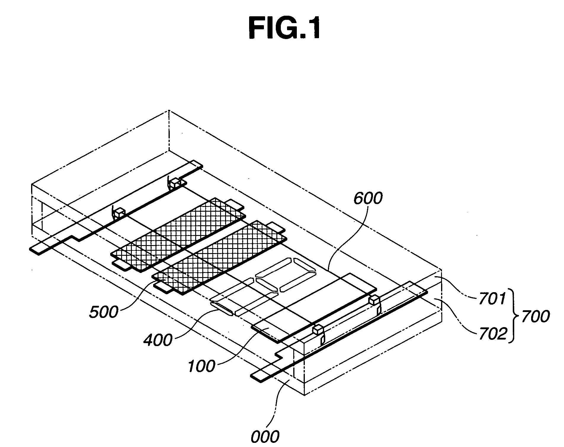
[0083] In the embodiment 1, FIG. 1 shows a fluorescent display tube of the present invention in which a gas occlusion material containing zircnium dioxide is disposed as a gas occlusion layer on the upper surface of the anode substrate in a fluorescent display tube.

[0084] As shown in FIG. 1, an aluminum thin film is formed on the upper surface of the glass substrate 000 of 25 mm in width×50 mm in length. Then, the aluminum thin film is patterned through the photolithographic process to form a wiring pattern (not shown). An insulating conductor 400 containing a low melting point glass as a main component, which has through holes for connecting the wiring pattern to the anode conductor 400, is formed on the upper surface of the wiring pattern. An anode conductor 300 containing graphite as a main component is formed and baked on the upper surface of the insulating layer (if necessary, conductive materials may be disposed in the through holes).

[0085] Thereafter, a fluorescent substanc...

embodiment 2

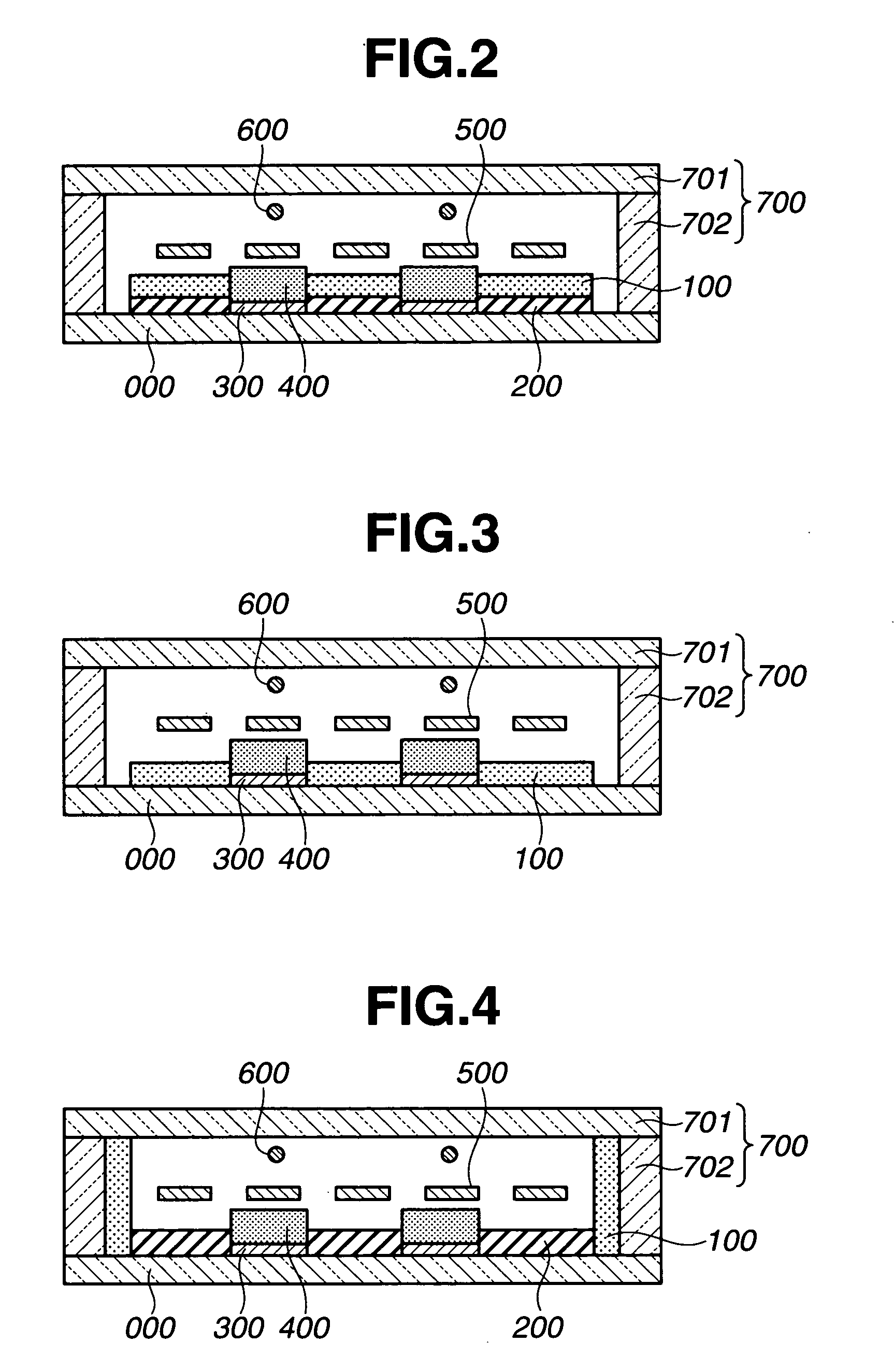
[0119]FIG. 2 shows a gas occlusion material disposed on the upper surface of an insulating layer containing a low melting point glass as a main component. Referring to FIG. 2, anodes 300 of an aluminum thin film are formed on the upper surface of the glass substrate 000. An insulating layer 200 containing a low melting point glass as a main component is formed on the upper surface of the anode and has openings in a display pattern. Each fluorescent substance layer 400 is formed on the upper surface of the anode. Using the screen printing process, a paste of zirconium dioxide used in the embodiment 1 is coated on the upper surface of the insulating layer 200 disposed around the fluorescent substance layers and in areas lacking fluorescent substance layers. Thus, the gas absorption layer 100 acting as a gas occlusion material is formed. Thereafter, a fluorescent display tube similar to that in the embodiment 1 was fabricated.

[0120] In the embodiment 2, the gas occlusion layer is disp...

embodiment 3

[0121]FIG. 3 shows a gas occlusion material, in place of an insulating layer containing a low melting point glass as a main component. Referring to FIG. 3, anodes 300 of an aluminum film are formed in a display pattern on the upper surface of the glass substrate 000. A fluorescent substance layer 400 is formed on the upper surface of each anode. Using the screen printing process, a paste of zirconium dioxide used in the embodiment 1 is coated at a portion, lacking anodes having openings in a display pattern, and on the upper surface of the insulating glass substrate. Thus, a gas occlusion layer 100 acting as a gas occlusion material is formed. Thereafter, a fluorescent display tube similar to that in the embodiment 1 was fabricated.

[0122] In the embodiment 3, the fluorescent display tube in the embodiment 2, which does not use the Ba-Al getter, and which is disposed such that the surface of the gas occlusion layer is exposed in a vacuum atmosphere, showed an effect similar to that ...


PUM


Abstract

A vacuum retention agent, which is safe, easy to handle, saves space, and absorbs residual gases inside a hermetic envelope to maintain the hermetic envelope in a high degree of vacuum is provided in place of the conventional metal getter. A display device including the vacuum retention agent is provided. A gas occlusion material containing ZrOx (where 1≦×≦2) is disposed in a hermetic envelope forming a self-luminous element. ZrOx is formed in pattern from a paste of zirconium dioxide, which can be generally obtained as a reagent. In a production step, the patterned self-luminous element is hermetically sealed in vacuum in an atmosphere at 120° C. to 500° C., so that the vacuum retention effect is more improved.

Description

CROSS REFERENCES TO RELATED APPLICATIONS [0001] This application claims the priority benefit of Japanese Patent Application No. 2004-017709 filed on Jan. 26, 2004. STATEMENT REGARDING FEDERALLY SPONSORED RESEARCH [0002] Not Applicable. BACKGROUND OF THE INVENTION [0003] 1. Field of the Invention [0004] The present invention relates to self-luminous elements including a fluorescent substance layer having fluorescent substances in a hermetic enclosure, where a fluorescent substance light-emits due to electron beam excitation. Particularly, the present invention relates to self-luminous elements, each having a new gas occlusion material for occluding unnecessary gases, which is disposed in an envelope to make and maintain a high degree of vacuum degree inside the enclosure. [0005] 2. Description of the Prior Art [0006] In self-luminous elements, an envelope is hermetically sealed to maintain the inside thereof in a hermetic state. Such a closed space is maintained to a high degree of v...

Claims


Application Information

Patent Timeline
IPC IPC(8): H01J9/39H01J1/62H01J7/18H01J9/00H01J9/24H01J17/24H01J29/04H01J29/86H01J29/94H01J31/12H01J31/15H01J63/02H01J63/04H01J63/06
CPCH01J7/183H01J63/06H01J63/04H01J63/02E05D15/466E05Y2201/686E05Y2900/148
Inventor SHIRAGA, TAKAOTAKANASHI, HIROKAZUUZAWA, YOSHIMASAKAGAWA, YOSHITAKA
Owner FUTABA CORPORATION
Learn More