
Anti-ballistic nanotube structures

a nanotube and ballistic technology, applied in the field of material structures, can solve the problems of high strain to failure of ductile materials, carbon nanotubes offer high elastic modulus, etc., and achieve optimal impact range, high fatigue and fracture strength characteristics, and high elastic modulus

Inactive Publication Date: 2005-07-21
LOCKHEED MARTIN CORP
View PDF0 Cites 19 Cited by
  • Summary
  • Abstract
  • Description
  • Claims
  • Application Information

AI Technical Summary

Benefits of technology

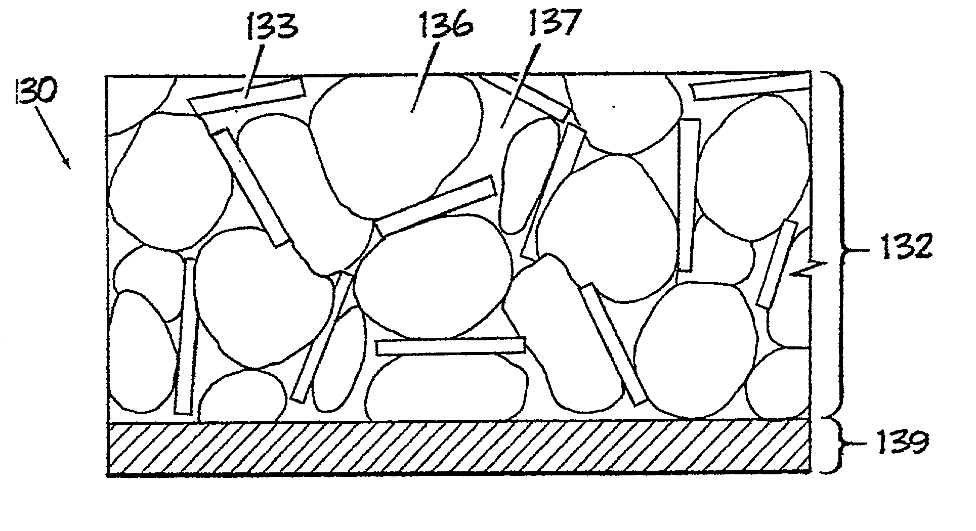
[0010] For the present invention, the aspect of including single-walled carbon nanotubes into an armored system provides for lightweight protection that also includes high fatigue and fracture strength characteristics capable of sustaining an optimal range of impacts from ballistic elements. For example, carbon nanotubes offer a high elastic modulus and a high strain to failure of a ductile material. Single-walled carbon nanotubes are a type of carbon nanotube. Carbon nanotubes typically are a hollow, tubular type of fullerene structure. Fullerenes, including the popular Buckeyball, are one of the three common allotropes of carbon that also include diamonds, and graphite.
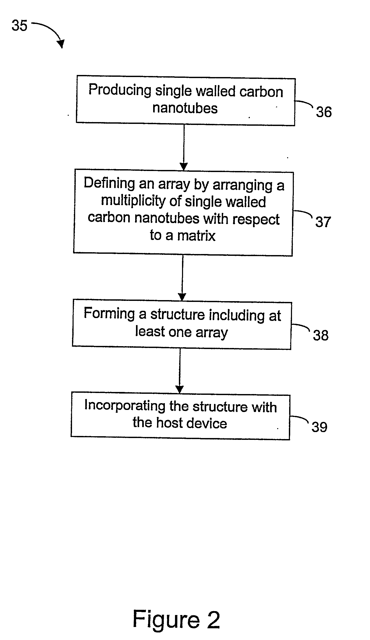
[0012] Aspects of the invention are found in a structure arrangement and method for the protection of a host against an impacting ballistic element and for providing ease of mobility. In one exemplary embodiment, the structure arrangement includes a composite disposed on a substrate and a w substrate coupled to the host. As such, the structure arrangement is directed toward a laminate for application with a host. In yet another exemplary embodiment, the structure arrangement is directed to a predetermined component or structure formed by single-walled carbon nanotubes so that the structure is ultimately incorporated with a host. It should be added that the host may be any suitable system and personnel for receiving ballistic protection and increased mobility due to the strong, lightweight characteristics of single-walled carbon nanotubes.

Problems solved by technology

For example, carbon nanotubes offer a high elastic modulus and a high strain to failure of a ductile material.

Method used


Image

  • Anti-ballistic nanotube structures
  • Anti-ballistic nanotube structures
  • Anti-ballistic nanotube structures

Examples


Embodiment Construction

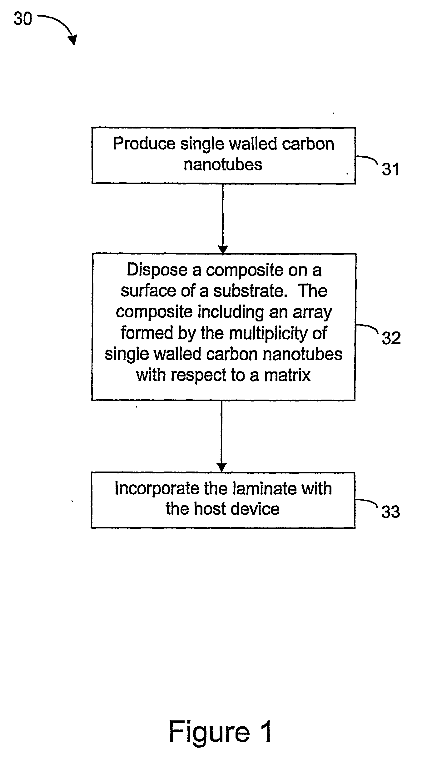
[0040] As required, detailed embodiments of the present invention are disclosed herein, however, it is to be understood that the disclosed embodiments are merely exemplary of the invention, which may be embodied in various forms. FIG. 1 is a schematic diagram of a method 30 for protection against an impacting ballistic element and for providing ease of mobility in an exemplary aspect of the invention. In particular, the method 30 produces a composite laminate that includes a multiplicity of single-walled carbon nanotubes for integration with a host device.

[0041] For the method 30 of FIG. 1, single-walled carbon nanotubes are produced via step 31. In one exemplary embodiment, single-walled carbon nanotubes are produced by electric-arc discharge procedures. In another exemplary embodiment single-walled carbon nanotubes are produced by methods of resistive heating. And in yet another exemplary embodiment, single-walled carbon nanotubes are produced by laser ablation processes. It shou...


PUM

PropertyMeasurementUnit
Sizeaaaaaaaaaa
Sizeaaaaaaaaaa
Sizeaaaaaaaaaa

Abstract

A structure arrangement and method for the protection of a host system against an impacting ballistic element and for providing ease of mobility. The structure arrangement includes a composite. The composite includes a matrix and a multiplicity of single-walled carbon nanotubes. The single-walled carbon nanotubes are arranged with respect to the matrix so as to define an array for engagement with an impacting ballistic element.

Description

BACKGROUND OF THE INVENTION [0001] I. Field of the Invention [0002] The present invention generally relates to material structures that include ductile, lightweight, high fatigue strength and high fracture strength characteristics. More particularly, this invention relates to a system and method for providing ease of mobility and protecting a host against an impacting ballistic element. [0003] II. Detailed Description of the Prior Art [0004] Many typical examples of systems, such as airplanes, spacecraft, cars, tanks, boats, buildings and personnel are subjected to ballistic impact by projectiles. For example, among others, a ballistic element includes a bullet directed at personnel, an artillery shell impacting a tank, a missile fired at a ship, a high speed particle hitting a satellite, and flying debris impacting an automobile or window. Impacts by ballistic elements often result in catastrophic or terminal damage to these systems. To mitigate or prevent impact damage, structural...

Claims


Application Information

Patent Timeline
IPC IPC(8): C01B31/02F41H5/04
CPCB82Y30/00B82Y40/00C01B31/0233Y10T428/30F41H5/04F41H5/0478Y10S428/913C01B2202/02F41H1/02F41H5/02F41H5/0492C01B32/162
Inventor RHOADS, JAMES E.HERMAN, FREDERICK J.YANAROS, JOHN O. JR.HENN, DAVID S.
Owner LOCKHEED MARTIN CORP
Learn More