
Method and data processing system having dynamic profile-directed feedback at runtime

a data processing system and dynamic profile technology, applied in the field of data processing, can solve the problems of low-level performance issues such as hardware allocation of shared resources among multiple threads, and is not addressed by conventional software-only performance optimization techniques, and conventional os schedulers and wlms do not implement fine-grained optimization of process thread execution

Inactive Publication Date: 2005-07-14
IBM CORP
View PDF13 Cites 88 Cited by
  • Summary
  • Abstract
  • Description
  • Claims
  • Application Information

AI Technical Summary

Benefits of technology

[0009] The present invention recognizes that the performance optimizations achieved through conventional OS schedulers and WLMs, while certainly resulting in performance improvements, optimize only to a certain level of granularity. That is, because schedulers and WLMs are software components, the optimizations achieved by these components tend to address high-level performance issues that can readily be monitored by software. As such, low-level performance issues, such as hardware allocation of shared resources among multiple threads, are not addressed by conventional software-only techniques of performance optimization.

Problems solved by technology

As such, low-level performance issues, such as hardware allocation of shared resources among multiple threads, are not addressed by conventional software-only techniques of performance optimization.
However, conventional OS schedulers and WLMs do not implement fine-grained optimization of the execution of process threads in accordance with the time-varying behavior of the threads.

Method used


Image

  • Method and data processing system having dynamic profile-directed feedback at runtime
  • Method and data processing system having dynamic profile-directed feedback at runtime
  • Method and data processing system having dynamic profile-directed feedback at runtime

Examples


Embodiment Construction

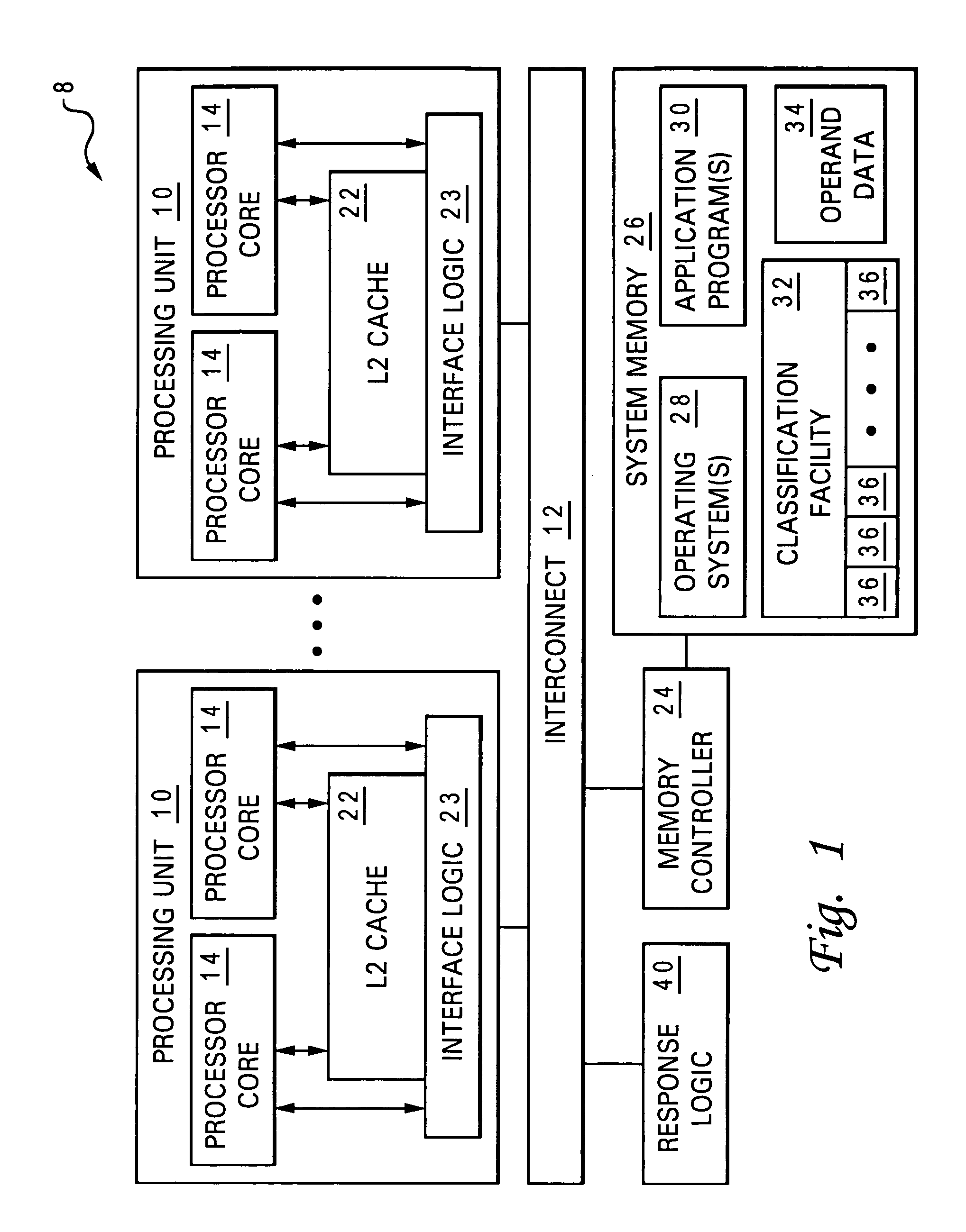
[0020] With reference now to the figures and in particular with reference to FIG. 1, there is illustrated a high-level block diagram of a multiprocessor (MP) data processing system that provides improved performance optimization in accordance with one embodiment of the present invention. As depicted, data processing system 8 includes multiple (e.g., 8, 16, 64 or more) processing units 10 coupled for communication by a system interconnect 12. Each processing unit 10 is a single integrated circuit including interface logic 23 and one or more processor cores 14.

[0021] As further illustrated in FIG. 1, the memory hierarchy of data processing system 8 includes one or more system memories 26, which form the lowest level of volatile data storage in the memory hierarchy, and one or more levels of cache memory, such as on-chip level two (L2) caches 22, which are utilized to stage instructions and operand data from system memory 26 to processor cores 14. As understood by those skilled in the...


PUM


Abstract

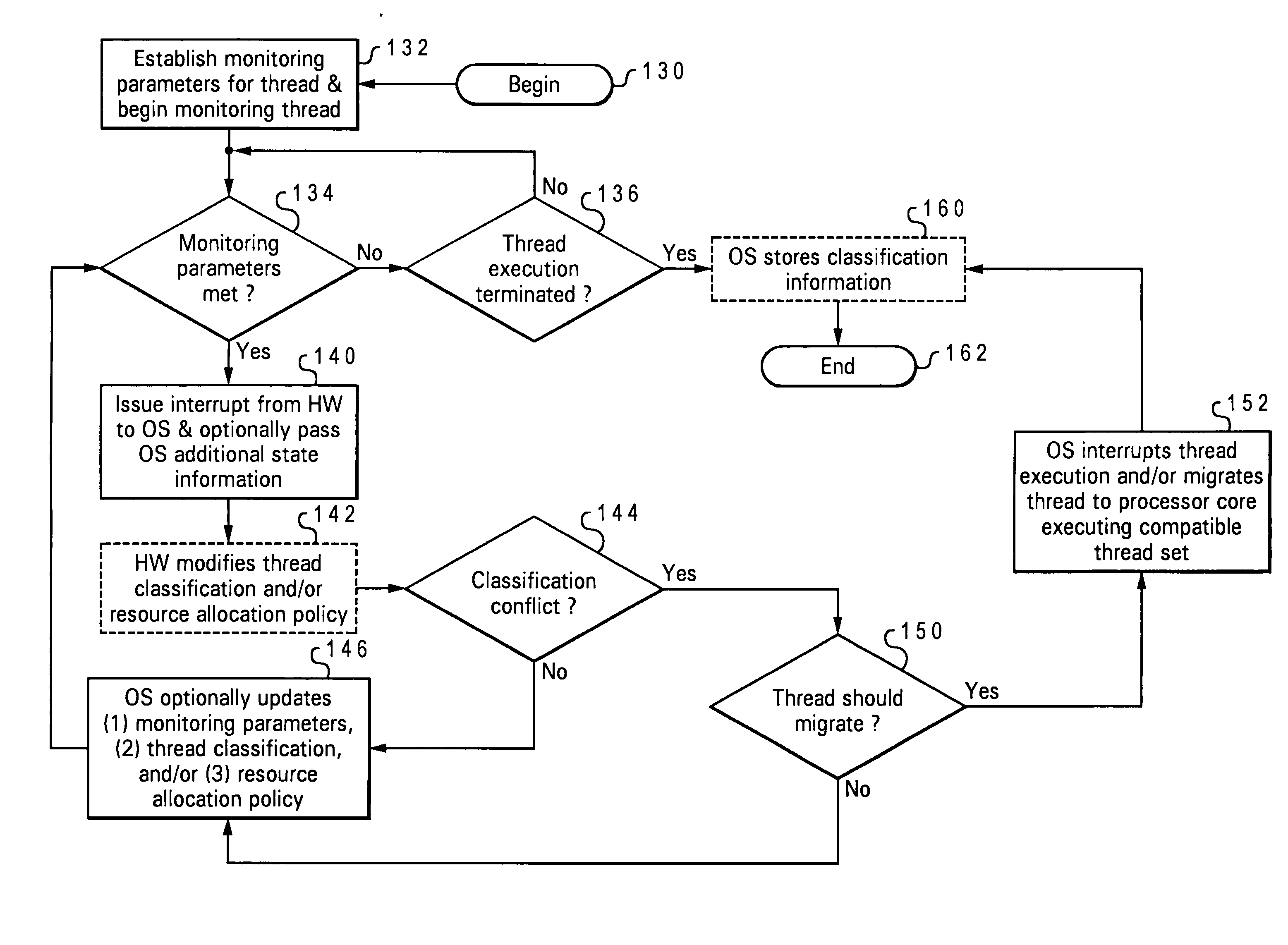
According to a method of operating a data processing system, software communicates to a processing unit a classification each of at least one schedulable software entity that the processing unit executes. A resource manager within the processing unit dynamically allocates hardware resources within the processing unit to the schedulable software entity during execution in accordance with the classification of the at least one schedulable software entity. The classification may be retrieved by the software from in data storage, and operating system software may schedule the schedulable software entity for execution by reference to the classification. The processing unit may also monitor, in hardware, execution of each of a plurality of schedulable software entities within the processing unit in accordance with a monitoring parameter set among one or more monitoring parameter sets. The processing unit may then report to software the utilization of hardware resources by each of the plurality of schedulable software entities so that the software may develop or refine a classification for the schedulable software entity.

Description

CROSS-REFERENCE TO RELATED APPLICATION [0001] The present application is related to U.S. patent application Ser. No. 10 / ______ (Docket No. AUS920020207US1), which is filed on even date herewith, assigned to the assignee of the present application, and incorporated herein by reference in its entirety.BACKGROUND OF THE INVENTION [0002] 1. Technical Field [0003] The present invention relates in general to data processing, and in particular, to performance optimization within a data processing system. Still more particularly, the present invention relates to a data processing system and method in which hardware and software coordinate to optimize processing of threads. [0004] 2. Description of the Related Art [0005] A number of trends currently influence the development of server-class and mainframe computer systems. In particular, transistor densities within integrated circuits continue to increase according to Moore's Law, which in its current formulation posits that the number of tra...

Claims


Application Information

Patent Timeline
Patent Type & Authority Applications(United States)
IPC IPC(8): G06F9/30
CPCG06F2209/507G06F9/5011
Inventor ARIMILLI, RAVI KUMARSWANBERG, RANDAL CRAIG
Owner IBM CORP
Learn More