Semiconductor device and manufacturing method thereof

a technology of semiconductor devices and manufacturing methods, applied in semiconductor devices, semiconductor/solid-state device details, electrical apparatus, etc., can solve the problems of failure to blow fuse, yield and reliability, and invite fuse corrosion, so as to prevent overetching of dielectric films and better control of etching

Inactive Publication Date: 2005-07-14
RENESAS TECH CORP
View PDF10 Cites 7 Cited by
  • Summary
  • Abstract
  • Description
  • Claims
  • Application Information

AI Technical Summary

Benefits of technology

[0016] Accordingly, an object of the present invention is to provide a technique for optimizing the thickness of a dielectric film lying over a fuse by providing better control over etching of the dielectric film arranged over a semiconductor substrate.
[0017] Another object of the present invention is to provide a technique for preventing overetching of a dielectric film lying under a lower-level wiring even when a through hole for connecting upper-level and lower-level wirings is formed by etching an interlayer dielectric film while the lower-level wiring and the through hole stay relatively misregistered.

Problems solved by technology

After intensive investigations, however, the present inventors have found for the first time that the following problems are inherent in the conventional techniques.
Specifically, if the dielectric film covering the fuse is excessively thick, the fuse cannot be blown due to insufficient energy, even when laser light is applied to the fuse from above.
In contrast, an excessively thin dielectric film lying over the fuse may invite corrosion of the fuse, since such a thin dielectric film may allow water and other contaminants to penetrate the dielectric film lying over the fuse and reach the fuse.
Thus, the control of the thickness of the dielectric film covering the fuse is a key factor affecting the yield and reliability of the resulting semiconductor device.
In the formation of a through hole for connecting upper-level and lower-level wirings by etching an interlayer dielectric film, misregistration in relative positions of the lower wiring and the through hole may occur due to misregistration of a photomask.
This misregistration problem is becoming increasingly serious, since the wiring dimensions are being reduced more and more with an increase in the packing densities of semiconductor devices.

Method used


Image

  • Semiconductor device and manufacturing method thereof
  • Semiconductor device and manufacturing method thereof
  • Semiconductor device and manufacturing method thereof

Examples


first embodiment

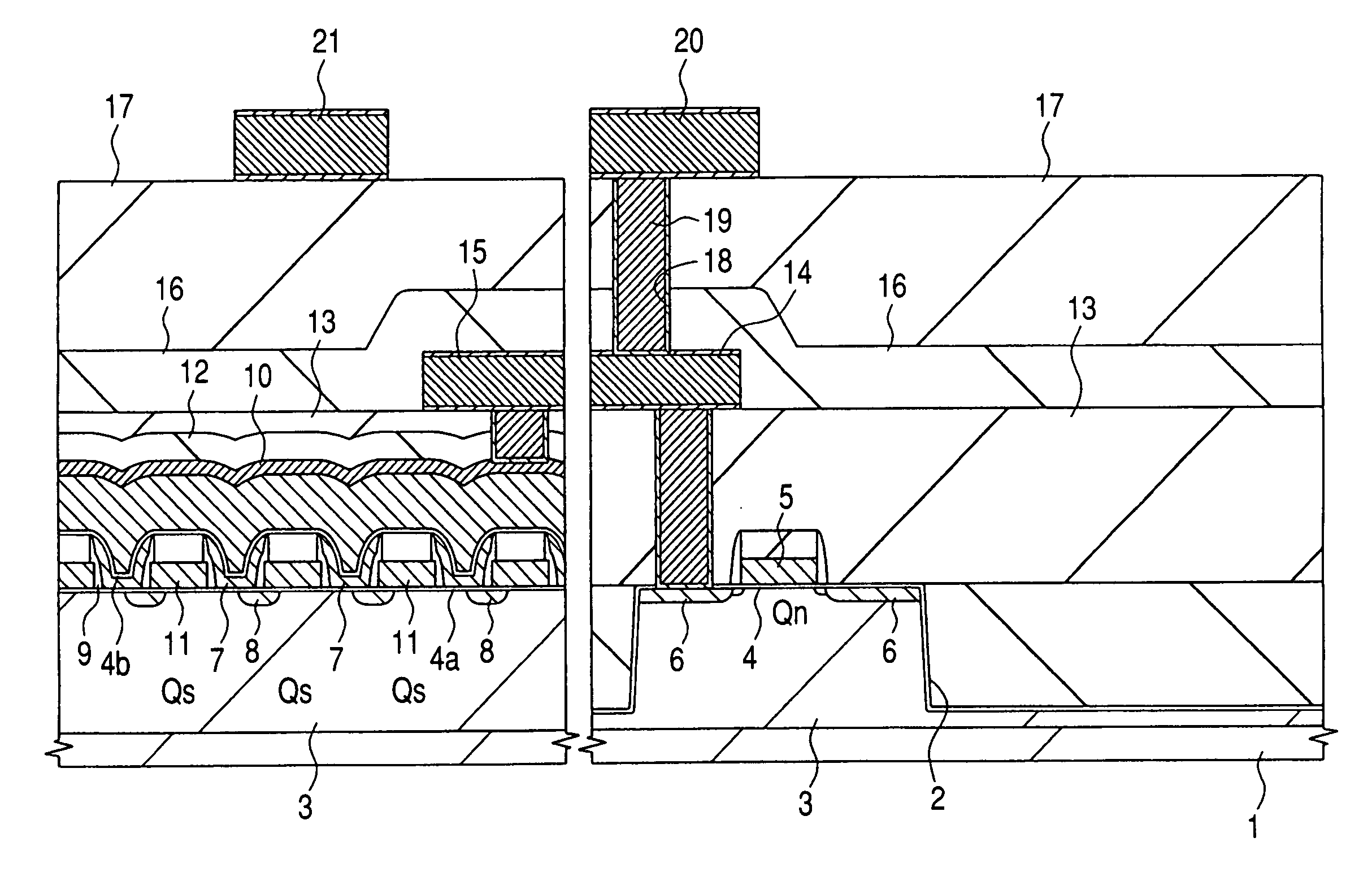
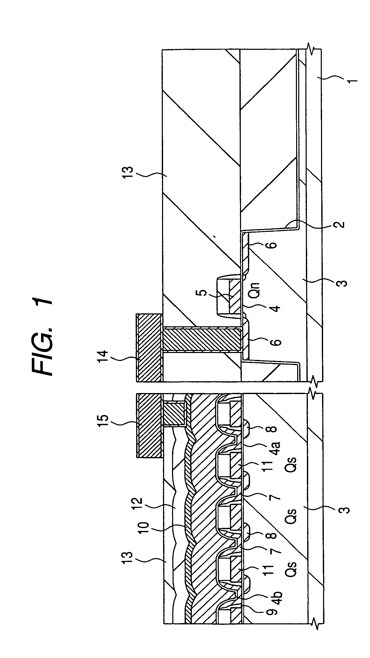
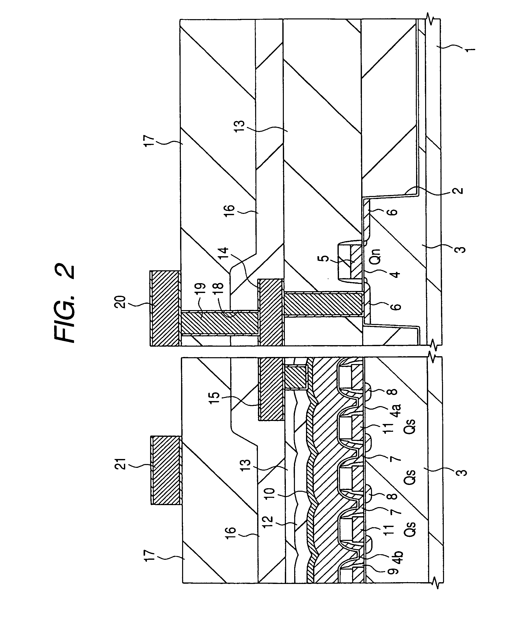
[0041] A method of manufacturing a semiconductor device will be sequentially described, step by step with reference to FIGS. 1 to 11. In the method, an opening is formed in a dielectric film arranged over a fuse. The left-hand parts in individual sectional views each represent a fuse-forming region and the right-hand parts thereof represent a bonding pad (hereinafter referred to as a “pad”) forming region.

[0042] With reference to FIG. 1, a device isolation trench 2, a p-type well 3, memory cells Qs serving as a flash memory, and an n-channel MISFET Qn serving as a peripheral circuit, for example, are initially formed on a semiconductor substrate (hereinafter referred to as a “substrate”) 1 according to conventional manufacturing processes. The substrate 1 comprises, for example, a p-type single-crystal silicon. Next, dielectric films, such as silicon oxide films 12 and 13, are formed over the memory cells Qs and the n-channel MISFET Qn by chemical vapor deposition (CVD). First-leve...

second embodiment

[0061] Another method of manufacturing a semiconductor device will be described with reference to FIGS. 12 to 16. In this method, a through hole is formed in a dielectric film over wirings.

[0062] Initially, as seen with reference to FIG. 12, a device isolation trench 2, a p-type well 3, an n-channel MISFET Qn and other components are formed on a substrate 1 according to conventional manufacturing procedures. A dielectric film, such as a silicon oxide film 13, is formed on the n-channel MISFET Qn by CVD, a surface of the silicon oxide film 13 is planarized by chemical mechanical polishing, and an SRO film 28 is formed over the silicon oxide film 13. The thickness of the SRO film 28 is set, for example, at about 70 nm. The SRO film 28 has the same configuration and is formed by the same manufacturing procedure as used in the First Embodiment.

[0063] With reference to FIG. 13, the SRO film 28 and the silicon oxide film 13 are dry-etched to form a contact hole 40, a metal plug 41 is ch...


PUM


Abstract

A silicon-rich oxide (SRO) film is arranged over an uppermost third-level wiring in a semiconductor device. Then, a silicon oxide film and a silicon nitride film lying over the third-level wiring are dry-etched to expose part of the third-level wiring to thereby form a bonding pad and to form an opening over the fuse. In this procedure, the SRO film serves as an etch stopper. This optimizes the thickness of the dielectric films lying over the fuse.

Description

CROSS-REFERENCE TO RELATED APPLICATION [0001] The present application claims priority from Japanese Patent Application No. 2004-004509, filed on Jan. 9, 2004, the content of which is hereby incorporated by reference into this application. BACKGROUND OF THE INVENTION [0002] The present invention relates in general to techniques to be performed on semiconductor devices and to methods of manufacture thereof. More specifically, it relates to techniques which give better control over etching of dielectric films arranged over a semiconductor substrate. [0003] Japanese Unexamined Patent Publication No. 2001-332510 (patent document 1) discloses a technique for reducing damage and erosion inflicted upon a semiconductor substrate by reducing overetching of the semiconductor substrate even in the case of a contact hole having a large aspect ratio. Such a contact hole typically is formed by dry-etching a dielectric film that is formed over the semiconductor substrate, to thereby expose the semi...

Claims


Application Information

Patent Timeline
Patent Type & Authority Applications(United States)
IPC IPC(8): H01L21/28H01L23/522H01L21/3065H01L21/311H01L21/768H01L23/48H01L23/52H01L23/525H01L23/532
CPCH01L23/5258H01L23/53295H01L2924/0002H01L2924/00
Inventor HOSODA, NAOHIROKANAMITSU, KENJI
Owner RENESAS TECH CORP
Why Eureka
Try Eureka