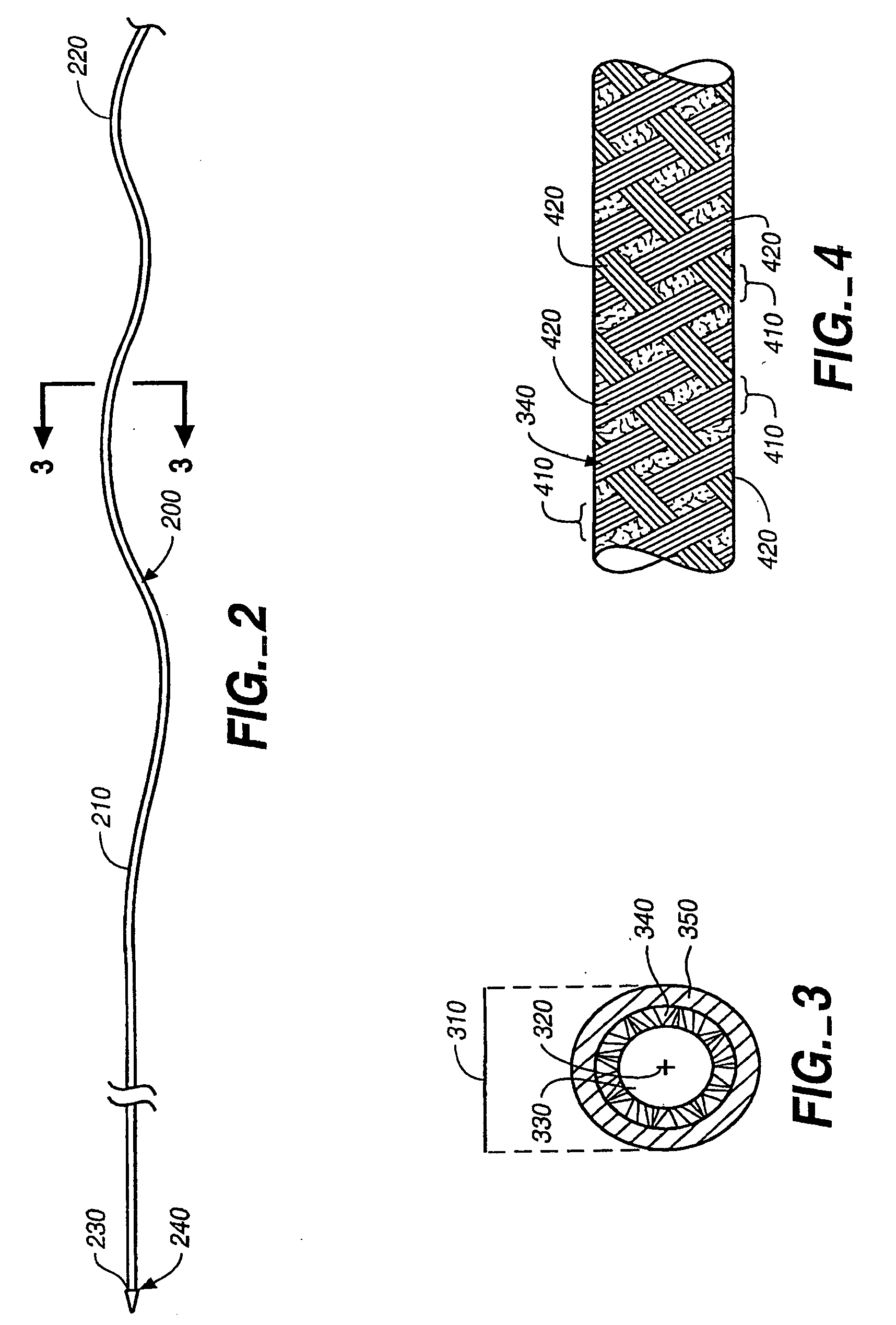
Ceramic reinforcement member for MRI devices

a technology of ceramic reinforcement and mri, applied in the direction of instruments, catheters, magnetic variable regulation, etc., can solve the problems of affecting the magnetic resonance (mr) image of the surrounding body tissue, alloy materials will still have some negative influence, and polymer fibers, compared to metal and metal alloy materials, have generally inferior mechanical qualities, and achieve minimal negative magnetic interference

Inactive Publication Date: 2005-07-07
BOSTON SCI SCIMED INC
View PDF18 Cites 18 Cited by
  • Summary
  • Abstract
  • Description
  • Claims
  • Application Information

AI Technical Summary

Benefits of technology

[0010] The present invention generally pertains to elongated intravascular MRI-related devices adapted to be advanced through a vessel of a subject. In particular, the present invention provides one or more constructions of such intravascular devices that incorporate reinforcement mechanisms that enable both desirable mechanical qualities and minimal negative magnetic interference with MR imaging.

Problems solved by technology

Elongated intravascular devices utilized in association with MRI applications must generally be made from low magnetic susceptible materials, otherwise they will disturb the magnetic resonance (MR) image of the surrounding body tissue.
In the context of MRI applications, however, all metal materials and metal alloy materials will still have some negative influence on the magnetic image.
Polymer fibers, however, as compared to the metal and metal alloy materials, have generally inferior mechanical qualities.

Method used


Image

  • Ceramic reinforcement member for MRI devices
  • Ceramic reinforcement member for MRI devices
  • Ceramic reinforcement member for MRI devices

Examples


Embodiment Construction

[0023]FIG. 1 is a partial block diagram of an illustrative magnetic resonance imaging and intravascular guidance system in which embodiments of the present invention could be employed. In FIG. 1, subject 100 on support table 110 is placed in a homogeneous magnetic field generated by magnetic field generator120. Magnetic field generator 120 typically comprises a cylindrical magnet adapted to receive subject 100. Magnetic field gradient generator 130 creates magnetic field gradients of predetermined strength in three mutually orthogonal directions at predetermined times. Magnetic field gradient generator 130 is illustratively comprised of a set of cylindrical coils concentrically positioned within magnetic field generator 120. A region of subject 100 into which a device 150, shown as a catheter, is inserted, is located in the approximate center of the bore of magnetic 120. Illustratively, device 150 could be a guidewire or some other intravascular device.

[0024] RF source 140 radiates...


PUM

PropertyMeasurementUnit
flexibilityaaaaaaaaaa
magnetic resonance imagingaaaaaaaaaa
MRIaaaaaaaaaa

Abstract

The present invention relates to a reinforced magnetic resonance imaging catheter. The catheter comprises a medical device having at least one lumen extending therethrough. The elongated body also includes a proximal end, a distal end, and circumference, a longitudinal axis running between the proximal and distal ends, and a coaxial layer that incorporates at least one elongated ceramic member that is substantially covered with a coating. An antenna is operably disposed proximate the distal end the medical device.

Description

[0001] The present application is a continuation of and claims priority of U.S. patent application Ser. No. 10 / 007,284, filed Nov. 9, 2001, the content of which is hereby incorporated by reference in its entirety.BACKGROUND OF THE INVENTION [0002] The present invention relates generally to intravascular devices used in magnetic resonance imaging. More particularly, the present invention relates to a ceramic reinforcement member for reinforcing elongated intravascular magnetic resonance imaging devices. [0003] Tracking of catheters and other devices positioned within a body may be achieved by means of a magnetic resonance imaging (MRI) system. Typically, such a magnetic resonance imaging system may be comprised of a magnet, a pulsed magnetic field gradient generator, a transmitter for electromagnetic waves in radio frequency (RF), a radio frequency receiver, and a controller. In a common implementation, an antenna is disposed either on the device to be tracked or on a guidewire or a ...

Claims


Application Information

Patent Timeline
Patent Type & Authority Applications(United States)
IPC IPC(8): G01R33/28A61B5/055A61L29/02A61L29/18A61M25/00A61M25/16
CPCA61B5/055A61L29/02G01R33/285A61M25/0045A61L29/18
Inventor WEBER, JAN
Owner BOSTON SCI SCIMED INC
Why Eureka
Try Eureka