Centerless grinder

a centerless grinder and grinder technology, applied in the direction of edge grinding machines, grinding machine components, manufacturing tools, etc., can solve the problems of manufacturing process delay, manufacturing process delay, grinding process breakage,

Active Publication Date: 2005-07-07
ROYAL MASTER GRINDERS INC
View PDF11 Cites 30 Cited by
  • Summary
  • Abstract
  • Description
  • Claims
  • Application Information

AI Technical Summary

Benefits of technology

[0012] In one embodiment, the present invention provides a centerless grinder without a regulating wheel. The centerless grinder of this first embodiment includes a grinding wheel having a working surface with a plurality of raised areas extending circumferentially around at least a portion of the working surface. The centerless grinder also includes a platform having an elongated top surface for supporting a workpiece substantially adjacent to the working surface. The platform has a front surface with a plurality of lateral grooves for receiving the raised areas on the working surface such that movement of the platform toward the working surface into a working area adjacent the grinding wheel enables the raised areas to pass into the lateral grooves and grind the workpiece.

Problems solved by technology

Highly abrasive particles ground from the workpiece typically collect on this surface.
As a result, the work rest blade must be replaced frequently during typical manufacturing operations resulting in delays in the manufacturing process.
Grinding each new work rest blade to such a specific profile further delays the manufacturing process.
If the work rest blade is made too narrow, moreover, it will break during the grinding process.
In addition, if the work rest blade is ground to a narrow profile to accommodate thin workpieces such as medical guide wires, the extent to which the regulating wheel can be backed away from the grinding wheel also is limited.
If the regulating wheel is moved too far away from the grinding wheel, moreover, the workpiece will slip off of the work rest blade resulting in damage to the workpiece and possible damage to the grinding / regulating wheel assembly.
Since the workpiece's forward movement between the grinding wheel and the regulating wheel is controlled by the regulating wheel's speed and tilt angle (among other factors), slight changes in either of these factors can result in errors in the workpiece's desired grinding profile.
Because of this thin width, the grinding wheel is fragile and prone to breaking.
Also, the grinding process is extremely slow, and the workpiece must be moved through the working area at a rate substantially slower than that for conventional centerless grinders.
As a result, the range of useful functions for this centerless grinder is severely limited.
These steps substantially delay the manufacturing process.
These steps also substantially delay the manufacturing process.

Method used


Image

  • Centerless grinder
  • Centerless grinder
  • Centerless grinder

Examples


Embodiment Construction

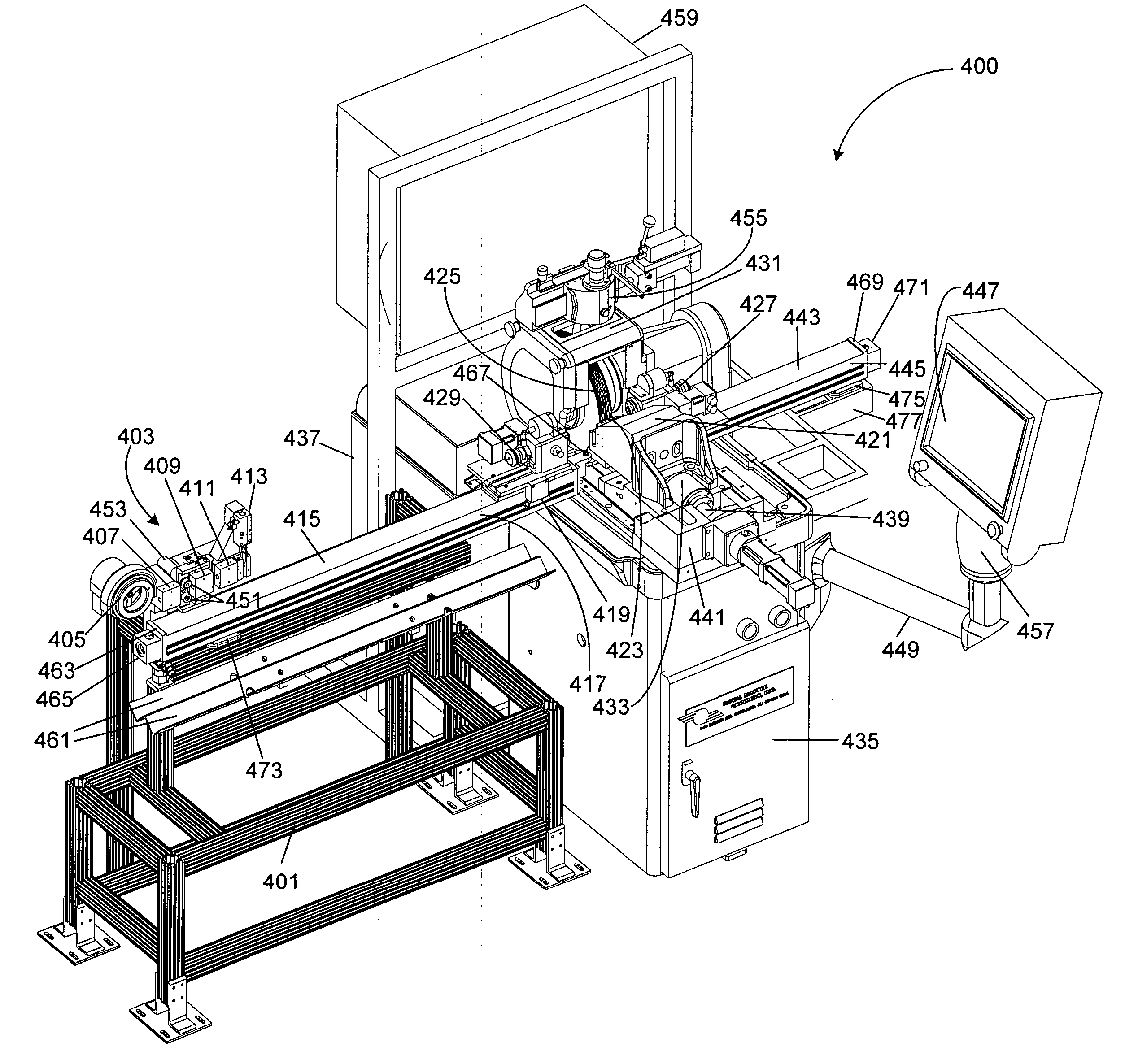
[0039] Perspective, front elevational, top plan, right side elevational and left side elevational views of a centerless grinder 400 in accordance with the present invention are shown and FIGS. 4, 5, 6A, 6B and 6C, respectively. Centerless grinder 400 can be used for grinding, for example, medical guide wires, rods, golf club shafts, antenna, fishing rods and a variety of small (an inch or less) metallic and nonmetallic parts. Centerless grinder 400 also can be used for grinding parts in accordance with severe or unusual grinding profiles (for example, a twisted helix) and parts made of materials that are hard to grind (for example, nickel titanium).

[0040] Centerless grinder 400 includes a grinding wheel (also called a work wheel) 425 which rotates on a shaft (not shown). Grinding wheel 425 is driven by a belt and is powered by an electric motor (not shown) enclosed within a housing 435. Housing 435 also encloses electronic controls and other electronics for centerless grinder 400. ...


PUM


Abstract

A centerless grinder for grinding an elongated workpiece includes a grinding wheel having a working surface with a plurality of raised areas extending circumferentially around at least a portion of the working surface. A platform is provided having an elongated top surface for supporting the workpiece substantially adjacent to the working surface of the grinding wheel and a front surface with a plurality of lateral grooves for receiving the raised areas on the working surface of the grinding wheel such that movement of the platform toward the working surface into a working area adjacent to the grinding wheel enables the raised areas to pass into the lateral grooves and grind the workpiece. The centerless grinder further includes a first spindle and collet in front of the working area and a second spindle and collet behind the working area, for grinding both ends of an elongated workpiece without removing the workpiece from the grinder, and a wire spool assembly for grinding wire stock directly from the wire spool.

Description

BACKGROUND OF THE INVENTION [0001] The present invention relates to centerless grinders. [0002] Centerless grinders are well known machines for grinding elongated cylindrical workpieces such as medical guide wires, rods, pins, golf club shafts, antenna, fishing rods and similar articles. Conventional centerless grinders include a supporting structure on which a grinding wheel and a regulating wheel are mounted with their working surfaces facing each other and slightly separated. The workpiece is positioned between these two wheels (“the working area”). These wheels rotate in the same direction about a substantially horizontal axis at different speeds. The axis of rotation of the regulating wheel is somewhat inclined from the horizontal plane, however, to provide a “tilt angle.” This tilt angle causes the workpiece to move forwardly through the working area as the workpiece is being ground to a particular profile by the grinding wheel. The profile is controlled by moving the regulati...

Claims


Application Information

Patent Timeline
Patent Type & Authority Applications(United States)
IPC IPC(8): B24B5/18B24B5/30B24B49/00
CPCB24B5/18Y10S451/909B24B5/30
Inventor MEMMELAAR, JOHN SR.JOBES, KEVINMORRIS, TODD
Owner ROYAL MASTER GRINDERS INC
Why Eureka
Try Eureka